Seagate ST9250412AS Momentus 7200 FDE.2 SATA Product Manual - Page 27
Drive mounting
 |
View all Seagate ST9250412AS manuals
Add to My Manuals
Save this manual to your list of manuals |
Page 27 highlights
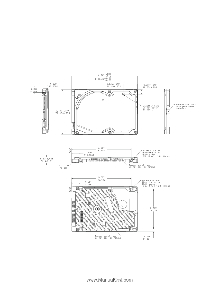
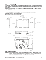
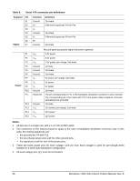
3.4 Drive mounting You can mount the drive using four screws in the side-mounting holes or four screws in the bottom-mounting holes. See Figure 4 for drive mounting dimensions. Follow these important mounting precautions when mounting the drive: • Allow a minimum clearance of 0.030 inches (0.76 mm) around the entire perimeter of the drive for cooling. • Use only M3 UNC mounting screws. • Do not overtighten the mounting screws. Maximum torque: 4.0 inch-lb (0.4519 N-m). • Four (4) threads (0.080 inches, 2.032 mm) minimum screw engagement recommended. • Avoid excessive drive distortion when mounting. Measurements shown in Figure 4 are in inches. Figure 4. Mounting dimensions Warning: FIPS 140-2 Models Contain 3 Tamper Evident Stickers with the marking "Tamper Indicator - Do Not Remove". These stickers must remain attached to provide the tamper evidence throughout the life of the drive. Removing these stickers will indicate tampering and void the drive warranty. Momentus 7200 FDE.2 SATA Product Manual, Rev. B 21
-
 1
1 -
2
-
3
-
4
-
5
-
6
-
7
-
8
-
9
-
10
-
11
-
12
-
13
-
14
-
15
-
16
-
17
-
18
-
19
-
20
-
21
-
 22
22 -
 23
23 -
 24
24 -
 25
25 -
 26
26 -
 27
27 -
 28
28 -
 29
29 -
 30
30 -
 31
31 -
 32
32 -
33
-
34
-
35
-
36
-
37
-
38
-
39
-
40
-
41
-
42
-
43
-
44
-
45
-
46
-
47
-
48
-
49
-
50
-
51
-
52
-
53
-
54
-
55
-
56
-
57
-
58
-
59
-
60
 |
 |