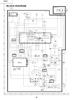
Sharp 20MR10 Service Manual - Page 10
Vertical-Size, V-Linearity and, V-S Correction Adjustments, Horizontal Position Adjustment, Vertical
 |
View all Sharp 20MR10 manuals
Add to My Manuals
Save this manual to your list of manuals |
Page 10 highlights
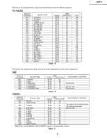
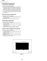
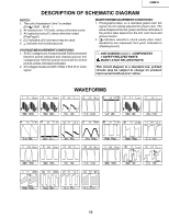
20MR10 Vertical-Size, V-Linearity and V-S Correction Adjustments 1. Receive a good local channel. 2. Enter the service mode DEF category and select the adjustment "D02" for Vertical Size, "D05" for VLinearity and "D06" for V-S Correction Adjustment. 3. Set in order "D05" for V-Linearity, "D06" for V-S Correction and set the data to get the best linearity. 4. Then adjust "D02" data until it become a proper vertical size. Horizontal Position Adjustment 1. Receive a good local channel. 2. Enter the service mode DEF category and select the adjustment "D01". 3. Adjust "D01" data value to center the picture. Vertical-Phase Adjustment 1. Receive a good local channel. 2. Enter the service mode DEF category and select the adjustment "D03". 3. Adjust "D03" bus data to get the most acceptable vertical position. Note: The step range is 20 (032) ±10steps. Caption Position Adjustment (Horizontal) 1. Receive a good local channel. 2. Enter the service mode DEF category and select the adjustment "D04". 3. A black text box will appear on the screen. (see Figure C. below) 4. Adjust "D04" data value to balance the text box position in the center (A=B). A B Figure C. 10
-
 1
1 -
2
-
3
-
4
-
 5
5 -
 6
6 -
 7
7 -
 8
8 -
 9
9 -
 10
10 -
 11
11 -
 12
12 -
 13
13 -
 14
14 -
 15
15 -
16
-
17
-
18
-
19
-
20
-
21
-
22
-
23
-
24
-
25
-
26
 |
 |