Sharp 20MR10 Service Manual - Page 5
Installation And Service Instructions
 |
View all Sharp 20MR10 manuals
Add to My Manuals
Save this manual to your list of manuals |
Page 5 highlights
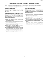
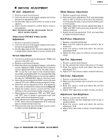
20MR10 INSTALLATION AND SER VICE INSTRUCTIONS Note: (1) When performing any adjustments to resistor controls and transformers use non-metallic screwdrivers or TV alignment tools. (2) Before performing adjustments, the TV set must be on at least 15 minutes. CIRCUIT PROTECTION The receiver is protected by a 4.0A fuse (F701), mounted on PWB-A, wired into one side of the AC line input. X-RADIATION PROTECT OR CIRCUIT TEST After service has been performed on the horizontal deflection system, high voltage system, B+system, test the X-Radiation protection circuit to ascertain proper operation as follows: 1. Apply 120V AC using a variac transformer for accurate input voltage. 2. Allow for warm up and adjust all customer controls for normal picture and sound. 3. Receive a good local channel. 4. Connect a digital voltmeter to TP653 and make sure that the voltmeter reads 21.4 ±1.5V. 5. Apply external 27.2V DC at TP653 by using an external DC supply, TV must be shut of f. 6. To reset the protector, unplug the AC cord and make a short circuit between TP651 and TP652. Now make sure that normal picture appears on the screen. 7. If the operation of the horizontal oscillator does not stop in step 5, the circuit must be repaired before the set is returned to the customer. HIGH VOLTAGE CHECK High voltage is not adjustable but must be checked to verify that the receiver is operating within safe and efficient design limitations as specified checks should be as follows: 1. Connect an accurate high voltage meter between ground and anode of picture tube. 2. Operate receiver for at least 15 minutes at 120V AC line voltage, with a strong air signal or a properly tuned in test signal. 3. Enter the service mode and select the service adjustment "S03" and Bus data "01" (Y-mute on). 4. The voltage should be approximately 26.0kV (at zero beam). If a correct reading cannot be obtained, check circuitry for malfunctioning components. After the voltage test, make Y-mute off to the normal mode. 5
-
 1
1 -
 2
2 -
 3
3 -
 4
4 -
 5
5 -
 6
6 -
 7
7 -
 8
8 -
 9
9 -
 10
10 -
 11
11 -
12
-
13
-
14
-
15
-
16
-
17
-
18
-
19
-
20
-
21
-
22
-
23
-
24
-
25
-
26
 |
 |