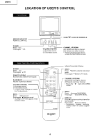
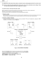
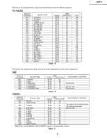
Sharp 20MR10 Service Manual - Page 3
Important Service Safety Precaution - manual
 |
View all Sharp 20MR10 manuals
Add to My Manuals
Save this manual to your list of manuals |
Page 3 highlights
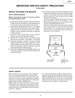
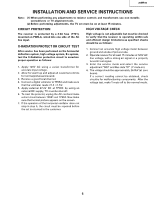
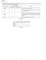
20MR10 IMPORTANT SER VICE SAFETY PRECAUTION (Continued) BEFORE RETURNING THE RECEIVER (Fire & Shock Hazard) Before returning the receiver to the user, perform the following safety checks. 1. Inspect all lead dress to make certain that leads are not pinched or that hardware is not lodged between the chassis and other metal parts in the receiver. 2. Inspect all protectivedevices such as non-metallic control knobs, insulating materials, cabinet backs, adjustment and compartment covers or shields, isolation resistor-capacity networks, mechanical insulators and etc. 3. To be sure that no shock hazard exists, check for leakage current in the following manner. Plug the AC cord directly into a 120 volt AC outlet, (Do not use an isolation transformer for this test). Using two clip leads, connect a 1.5k ohm, 10 watt resistor paralleled by a 0.15µF capacitor in series with all exposed metal cabinet parts and a known earth ground,such as electrical conduitor electrical ground connected to earth ground. Use an AC voltmeter having with 5000 ohm per volt, or higher, sensitivity to measure the AC voltage drop across the resistor. Connect the resistorconnection to all exposed metal parts having a return to the chassis (antenna, metal cabinet, screw heads, knobs and control shafts, escutcheon and etc.) and measure the AC voltage drop across the resistor. AII checks must be repeated with the AC line cord plug connection reversed. (If necessary, a nonpolarized adapter plug must be used only for the purpose of completing these check.) Any current measured must not exceed 0.5 milliamp. Any measurements not within the limits outlined above indicate of a potential shock hazard and corrective action must be taken before returning the instrument to the customer. 1.5k ohm 10W 0.15 F TEST PR OBE TO EXPOSED METAL PARTS CONNECT TO KNOWN EARTH GR OUND SAFETY NOTICE Many electrical and mechanical parts in television recevers have special safety-related characteristics. These characteristics are often not evident from visual inspection, nor can protection afforded by them be necessarily increased by using replacement components rated for higher voltage, wattage and etc. Replacement parts which have these special safety characteristics are identified in this manual; electrical components havingsuch features are identified by " ! " and shaded areas in the Replacement Parts Lists and Schematic Diagrams. For continued protection, replacement parts must be identical to those used in the original circuit.The use of substitute replacement parts which do not have the same safety characteristics as the factory recommended replacement parts shown in this service manual, may create shock, fire, X-radiation or other hazards. 3
-
 1
1 -
 2
2 -
 3
3 -
 4
4 -
 5
5 -
 6
6 -
 7
7 -
 8
8 -
 9
9 -
10
-
11
-
12
-
13
-
14
-
15
-
16
-
17
-
18
-
19
-
20
-
21
-
22
-
23
-
24
-
25
-
26
 |
 |