Sharp 20MR10 Service Manual - Page 2
Important Ser Vice Safety Precaution - tv
 |
View all Sharp 20MR10 manuals
Add to My Manuals
Save this manual to your list of manuals |
Page 2 highlights
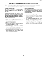
20MR10 IMPORTANT SERVICE SAFETY PRECAUTION Service work should be performed only by qualified service technicians who are thoroughly familiar withall safety checks and the servicing guidelines which follow: WARNING 1. For continued safety, no modification of any circuit should be attempted. 2. Disconnect AC powerbefore servicing. 3. Semiconductor heat sinks are potential shock hazards when the chassis is operating. 4. The chassis in this receiver has two ground systems whichare separated by insulating material. The nonisolated (hot) ground system is for the B+ voltage regulator circuit and the horizontal output circuit. The isolated ground system is for the low B+DC voltages and the secondary circuit of the high voltage transformer. To prevent electrical shock use an isolation transformer between the line cord and power receptacle, when servicing this chassis. 4A 125V CAUTION: FOR CONTINUED PROTECTION AGAINST A RISK OF FIRE, REPLACE ONLY WITH SAME TYPE 4A125V FUSE. SER VICING OF HIGH VOLTAGE SYSTEM AND PICTURE TUBE When servicing the high voltage system, remove the static charge by connecting a 10k ohm resistor in series withan insulated wire (such as a test probe) between the picture tube ground and the anode lead. (AC line cord should be disconnected from AC outlet.) 1. Picture tube in this receiver employs integral implosion protection. 2. Replace with tube of the same type number for continued safet.y 3. Do not lift picture tube by the neck. 4. Handle the picture tube only when wearing shatterproof goggles and after discharging the high voltage anode completely. X-RADIATION AND HIGH VOLTAGE LIMITS 1. Be sure all service personnel are aware of the procedures and instructions covering X-radiation. The only potential source of X-ray in current solid state TV receivers is the picture tube. However, the picture tube does not emit measurable X-Ray radiation, if the high voltage is as specified in the "High Voltage Check" instructions. It is only when high voltage is excessive that Xradiation is capable of penetrating the shell of the picture tube including the lead in the glass material. The important precaution is to keep the high voltage below the maximum level specified. 2. It is essential that servicemen have available at all times an accurate high voltage meter. The calibration of this meter should be checked periodically. 3. High voltage should alwaysbe kept at the rated value -no higher. Operation at higher voltages may cause a failure of the picture tube or high voltage circuitry and; also, under certain conditions, may produce radiation in exceeding of desirable levels. 4. When the high voltage regulator is operating properly there is no possibility of an X-radiation problem. Every time a colorchassis is serviced,the brightness should be tested while monitoring the high voltage witha meter to be certain that the high voltage does not exceed the specified value and that it is regulating correctly. 5. Do not use a picture tube other than that specified or make unrecommended circuit modifications to the high voltage circuitry. 6. When troubles hooting and taking test measurements on a receiver with excessive high voltage, avoid being unnecessarily close to the receiver. Do not operate the receiver longer than is necessary to locate the cause of excessive voltage. 2
-
 1
1 -
 2
2 -
 3
3 -
 4
4 -
 5
5 -
 6
6 -
 7
7 -
 8
8 -
9
-
10
-
11
-
12
-
13
-
14
-
15
-
16
-
17
-
18
-
19
-
20
-
21
-
22
-
23
-
24
-
25
-
26
 |
 |