Sharp LC-15B9U-S Service Manual - Page 12
Extension Cable 30-pin Main SC802-LCD Panel CN1
 |
View all Sharp LC-15B9U-S manuals
Add to My Manuals
Save this manual to your list of manuals |
Page 12 highlights
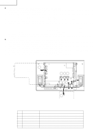
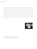
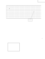
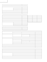
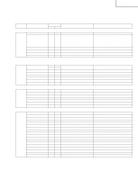
LC-13B8U-S LC-15B8U-S LC-15B9U-SM »Precautions in servicing the side B (backside) of the main PWB unit 1. Disconnect the FFC for connection between the main PWB (SC802) and LCD panel (CN1), and then connect the service-specific extension FFC (flat cable) (QCNW-B784WJZZ). 2. Disconnect the FFC for connection between the main PWB (SC801) and LCD panel (CN2), and then connect the service-specific extension FFC (flat cable) (QCNW-A556WJZZ). 3. Disconnect the FFC for connection between the main PWB (SC803) and LCD panel (CN3), and then connect the service-specific extension FFC (flat cable) (QCNW-A555WJZZ). 4. Disconnect the SC2001 side of the lead from between the main PWB (SC2001) and the sub PWB (P3401), and then connect the service-specific extension cable (QCNW-C461WJQZ). 5. Disconnect the SC2002 side of the lead from between the main PWB (SC2002) and the sub PWB (P3403), and then connect the service-specific extension cable (QCNW-C461WJQZ). 6. Disconnect the SC2003 side of the lead from between the main PWB (SC2003) and the sub PWB (P3404), and then connect the service-specific extension cable (QCNW-C461WJQZ). 7. Remove the lock screws (3 pcs.) from the main PWB, detach the PWB from the chassis frame, and then turn it over to service. »Precautions in servicing the Chip Parts side (backside) of the sub PWB unit 8. Disconnect the SC2001 side of the lead from between the main PWB (SC2001) and the sub PWB (P3401), and then connect the service-specific extension cable (QCNW-C461WJQZ). 9. Disconnect the SC2002 side of the lead from between the main PWB (SC2002) and the sub PWB (P3403), and then connect the service-specific extension cable (QCNW-C461WJQZ). 10. Disconnect the SC2003 side of the lead from between the main PWB (SC2003) and the sub PWB (P3404), and then connect the service-specific extension cable (QCNW-C461WJQZ). 11. Remove the lock screws (4 pcs.) from the sub PWB and then turn it over to service. 11 Sub PWB (Side-B) 10 9 8 P3404 P3403 P3401 SC2003 SC2002 SC2001 6 54 SC803 1 SC802 CN1 SC801 3 2 CN3 CN2 7 Main PWB (Side-B) Step 1 2 3 4, 8 5, 9 6, 10 Part No. QCNW-B784WJZZ QCNW-A556WJZZ QCNW-A555WJZZ QCNW-C461WJQZ QCNW-C461WJQZ QCNW-C461WJQZ Description Extension Cable 30-pin Main (SC802)-LCD Panel (CN1) Extension Cable 50-pin Main (SC801)-LCD Panel (CN2) Extension Cable 20-pin Main (SC803)-LCD Panel (CN3) Extension Cable 15-pin Main (SC2001)-Sub (P3401) Extension Cable 15-pin Main (SC2002)-Sub (P3403) Extension Cable 15-pin Main (SC2003)-Sub (P3404) 12
-
 1
1 -
2
-
3
-
4
-
5
-
6
-
 7
7 -
 8
8 -
 9
9 -
 10
10 -
 11
11 -
 12
12 -
 13
13 -
 14
14 -
 15
15 -
 16
16 -
 17
17 -
18
-
19
-
20
-
21
-
22
-
23
-
24
-
25
-
26
-
27
-
28
-
29
-
30
-
31
-
32
-
33
-
34
-
35
-
36
-
37
-
38
-
39
-
40
-
41
-
42
-
43
-
44
-
45
-
46
-
47
-
48
-
49
-
50
-
51
-
52
-
53
-
54
-
55
-
56
-
57
-
58
-
59
-
60
-
61
-
62
-
63
-
64
-
65
-
66
-
67
-
68
-
69
-
70
-
71
-
72
-
73
-
74
-
75
-
76
-
77
-
78
-
79
-
80
-
81
-
82
-
83
-
84
-
85
-
86
-
87
-
88
-
89
-
90
-
91
-
92
-
93
-
94
-
95
-
96
-
97
-
98
-
99
-
100
-
101
-
102
-
103
-
104
-
105
-
106
-
107
-
108
-
109
-
110
 |
 |
