Sharp LC-15B9U-S Service Manual - Page 9
Removing Of Major Parts
 |
View all Sharp LC-15B9U-S manuals
Add to My Manuals
Save this manual to your list of manuals |
Page 9 highlights
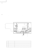
REMOVING OF MAJOR PARTS 1. Remove the stand cover fixing screw (1 pc.). 2. Remove the stand fixing screws (4 pcs.). 3. Remove the carrying handle fixing screws (4 pcs.). 4. Remove the terminal cover. 5. Remove the terminal screws (2 pcs.). (LC-13B8U-S) 5. Remove the terminal screws (4 pcs.). (LC-15B8U-S, LC-15B9U-SM) 6. Remove the cabinet B fixing screws (8 pcs.). (LC-13B8U-S) 6. Remove the cabinet B fixing screws (7 pcs.). (LC-15B8U-S, LC-15B9U-SM) 7. Remove the cabinet B after opening from the direction of an arrow. 8. Disconnect all the connectors from all the PWBs. Cabinet B Cabinet A 6 Carrying Handle LC-13B8U-S LC-15B8U-S LC-15B9U-SM 3 2 1 Stand Cover 5 7 5 Only for 5 LC-15B8U-S, LC-15B9U-SM 4 6 Only for LC-13B8U-S Terminal Cover Stand Sub PWB P6700 8 P6701 P6702 P6703 8 P3404 P3403 P3401 8 8 8 SC802 SC2003 SC2002 SC2001 CN1 P3302:15" 8 P3303:13" P2001 SC803 SC801 R/C, LED PWB SC4001 CN3 CN2 8 8 Main PWB 9
-
 1
1 -
2
-
3
-
 4
4 -
 5
5 -
 6
6 -
 7
7 -
 8
8 -
 9
9 -
 10
10 -
 11
11 -
 12
12 -
 13
13 -
 14
14 -
15
-
16
-
17
-
18
-
19
-
20
-
21
-
22
-
23
-
24
-
25
-
26
-
27
-
28
-
29
-
30
-
31
-
32
-
33
-
34
-
35
-
36
-
37
-
38
-
39
-
40
-
41
-
42
-
43
-
44
-
45
-
46
-
47
-
48
-
49
-
50
-
51
-
52
-
53
-
54
-
55
-
56
-
57
-
58
-
59
-
60
-
61
-
62
-
63
-
64
-
65
-
66
-
67
-
68
-
69
-
70
-
71
-
72
-
73
-
74
-
75
-
76
-
77
-
78
-
79
-
80
-
81
-
82
-
83
-
84
-
85
-
86
-
87
-
88
-
89
-
90
-
91
-
92
-
93
-
94
-
95
-
96
-
97
-
98
-
99
-
100
-
101
-
102
-
103
-
104
-
105
-
106
-
107
-
108
-
109
-
110
 |
 |
