Sharp PN-655UP PNG655U Operation Manual - Page 34
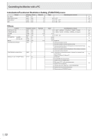
Initialization/Functional Restriction Setting FUNCTION menu, Others, Controlling the Monitor with
 |
View all Sharp PN-655UP manuals
Add to My Manuals
Save this manual to your list of manuals |
Page 34 highlights
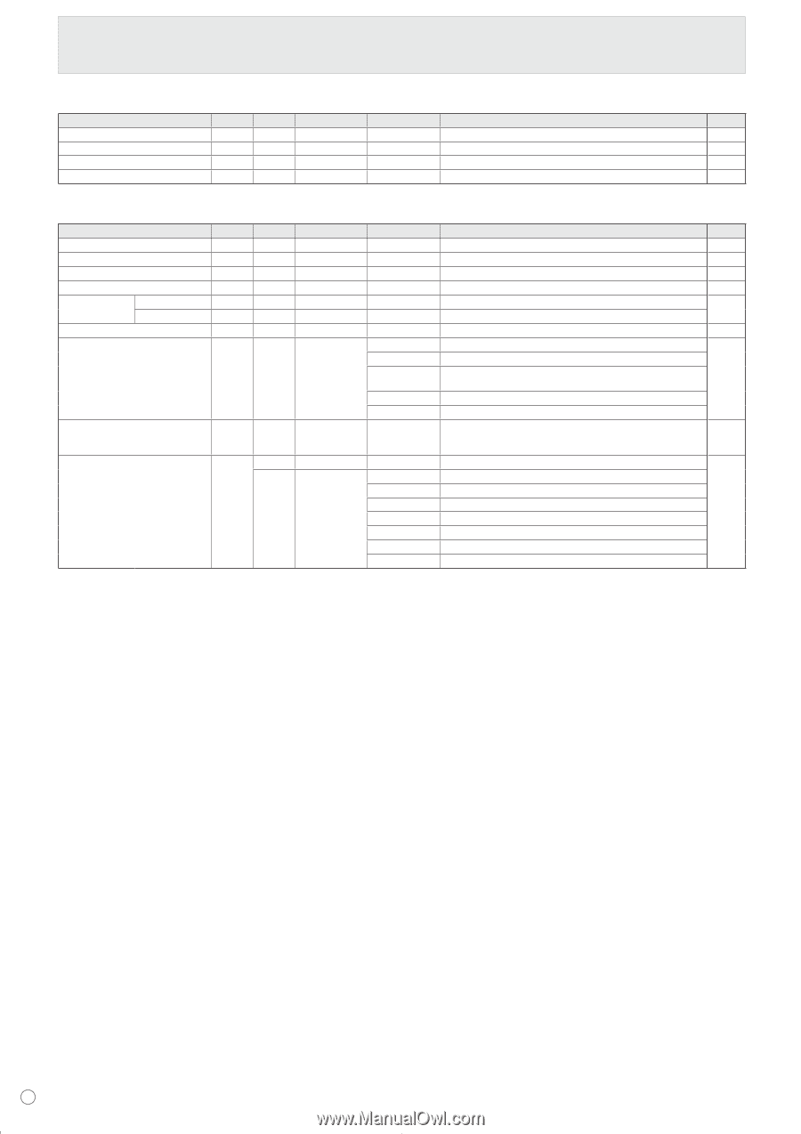
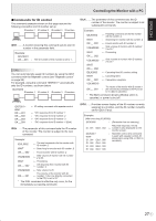
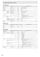
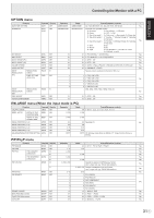
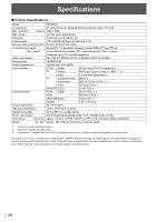
Controlling the Monitor with a PC Initialization/Functional Restriction Setting (FUNCTION) menu ALL RESET Functio Command Direction RSET W Parameter 0 Reply Control/Response contents * No ADJUSTMENT LOCK ALCK WR 0-2 0-2 0: OFF Yes OSD DISPLAY LOSD WR 0-1 0-1 0: ON, 1: OFF Yes LED OFLD WR 0-1 0-1 0: ON, 1: OFF Yes Others Function SCREEN SIZE (PC) SCREEN SIZE (AV) VOLUME MUTE INFORMATION BRIGHT MODEL SERIAL NO TEMPERATURE SENSOR Command Direction WIDE WR WIDE WR VOLM WR MUTE WR INF1 R SRNO R VLMP WR DSTA R Parameter 1-5 1-5 0-31 0-1 0-31 TEMPERATURE ACQUISITION ERRT R CAUSE OF LAST STANDBY MODE STCA W 0 R Reply Control/Response contents * 1-5 1: WIDE, 2: NORMAL, 3: DotbyDot, 4: ZOOM1, 5: ZOOM2 Yes 1-5 1: WIDE, 2: ZOOM1, 3: ZOOM2, 4: NORMAL, 5: DotbyDot Yes 0-31 Yes 0-1 0: OFF, 1: ON No Value Yes Value 0-31 Brightness Yes 0 Internal temperature normal 1 Internal temperature abnormal (Standby mode) 2 Internal temperature abnormal (Temperature is normal now, but it was abnormal during operation.) Yes 3 Internal temperature abnormal (Brightness of the backlight decreases.) 4 Temperature sensor abnormal Value Temperature at temperature sensors 1 through 3 are returned in the following forms: Yes [Sensor 1], [Sensor 2], [Sensor 3] Initialization 0 No detectable error has occurred 1 Standby mode by POWER button 2 Main power "OFF" by the main power switch Yes 3 Standby mode by RS-232C 4 Waiting mode by No Signal (Incl: VESA DPMS/DMPM) 6 Standby mode by abnormal temperature 8 Standby mode by SCHEDULE setting E 32
-
 1
1 -
2
-
3
-
4
-
5
-
6
-
7
-
8
-
9
-
10
-
11
-
12
-
13
-
14
-
15
-
16
-
17
-
18
-
19
-
20
-
21
-
22
-
23
-
24
-
25
-
26
-
27
-
28
-
 29
29 -
 30
30 -
 31
31 -
 32
32 -
 33
33 -
 34
34 -
 35
35 -
 36
36 -
 37
37 -
 38
38 -
 39
39 -
40
-
41
-
42
-
43
-
44
-
45
-
46
-
47
-
48
-
49
-
50
-
51
-
52
-
53
-
54
-
55
-
56
-
57
-
58
-
59
-
60
-
61
-
62
-
63
-
64
-
65
-
66
-
67
-
68
-
69
-
70
-
71
-
72
-
73
-
74
-
75
-
76
 |
 |