Sharp PN-655UP PNG655U Operation Manual - Page 38
PC/AV output terminal pins
 |
View all Sharp PN-655UP manuals
Add to My Manuals
Save this manual to your list of manuals |
Page 38 highlights
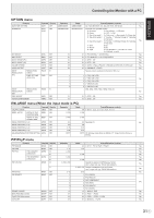
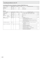
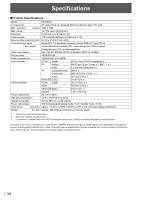
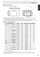
Specifications Power management This monitor conforms to VESA DPMS and DVI DMPM. Both your video card and computer must support the same standard in order for the monitor's power management function to work. DPMS: Display Power Management Signaling DMPM: Digital Monitor Power Management DPMS ON STATE STANDBY SUSPEND OFF STATE Screen Power consumption Hsync Display 550 W Yes No display 10 W No Yes No Vsync Yes Yes No No DMPM Monitor ON Active OFF Screen Display No display Power consumption 550 W 10 W DDC (plug and play) The monitor supports the VESA DDC (Display Data Channel) standard. DDC is a signal standard for plug and play between monitors and computers. Information about resolution and other parameters is exchanged between the two. This function can be used if the computer supports DDC and it has been configured to detect plug-and-play monitors. There are several types of DDC, depending on the communication method used. This monitor supports DDC2B. PC1/AV1 input terminal pins (DVI-D24 pin) PC2 input terminal pins (Mini D-sub 15 pin) No. Function 1 TMDS data 2- 2 TMDS data 2+ 3 TMDS data 2/4 shield 4 N.C. 5 N.C. 6 DDC clock 7 DDC data 8 N.C. 9 TMDS data 1- 10 TMDS data 1+ 11 TMDS data 1/3 shield 12 N.C. No. Function 13 N.C. 14 +5 V 15 GND 16 Hot-plug detection 17 TMDS data 0- 18 TMDS data 0+ 19 TMDS data 0/5 shield 20 N.C. 21 N.C. 22 TMDS clock shield 23 TMDS clock+ 24 TMDS clock- RS-232C input terminal pins (D-sub 9 pin) No. Function 1 N.C. 2 Transmitted data 3 Received data 4 N.C. 5 GND No. Function 6 N.C. 7 N.C. 8 N.C. 9 N.C. RS-232C output terminal pins (D-sub 9 pin) No. Function No. Function 1 Red video signal input 9 +5 V 2 Green video signal input 10 GND 3 Blue video signal input 11 N.C. 4 N.C. 12 DDC data 5 GND 13 Hsync signal input 6 GND for red video signal 14 Vsync signal input 7 GND for green video signal 15 DDC clock 8 GND for blue video signal PC/AV output terminal pins (DVI-D24 pin) No. Function 1 TMDS data 2- 2 TMDS data 2+ 3 TMDS data 2/4 shield 4 N.C. 5 N.C. 6 DDC clock 7 DDC data 8 N.C. 9 TMDS data 1- 10 TMDS data 1+ 11 TMDS data 1/3 shield 12 N.C. No. Function 13 N.C. 14 +5 V 15 GND 16 Hot-plug detection 17 TMDS data 0- 18 TMDS data 0+ 19 TMDS data 0/5 shield 20 N.C. 21 N.C. 22 TMDS clock shield 23 TMDS clock+ 24 TMDS clock- No. Function 1 N.C. 2 Received data 3 Transmitted data 4 N.C. 5 GND E 36 No. Function 6 N.C. 7 N.C. 8 N.C. 9 N.C.
-
 1
1 -
2
-
3
-
4
-
5
-
6
-
7
-
8
-
9
-
10
-
11
-
12
-
13
-
14
-
15
-
16
-
17
-
18
-
19
-
20
-
21
-
22
-
23
-
24
-
25
-
26
-
27
-
28
-
29
-
30
-
31
-
32
-
 33
33 -
 34
34 -
 35
35 -
 36
36 -
 37
37 -
 38
38 -
 39
39 -
 40
40 -
 41
41 -
 42
42 -
 43
43 -
44
-
45
-
46
-
47
-
48
-
49
-
50
-
51
-
52
-
53
-
54
-
55
-
56
-
57
-
58
-
59
-
60
-
61
-
62
-
63
-
64
-
65
-
66
-
67
-
68
-
69
-
70
-
71
-
72
-
73
-
74
-
75
-
76
 |
 |
