Sharp T19D1-B Operation Manual - Page 9
Product description
 |
UPC - 074000047808
View all Sharp T19D1-B manuals
Add to My Manuals
Save this manual to your list of manuals |
Page 9 highlights
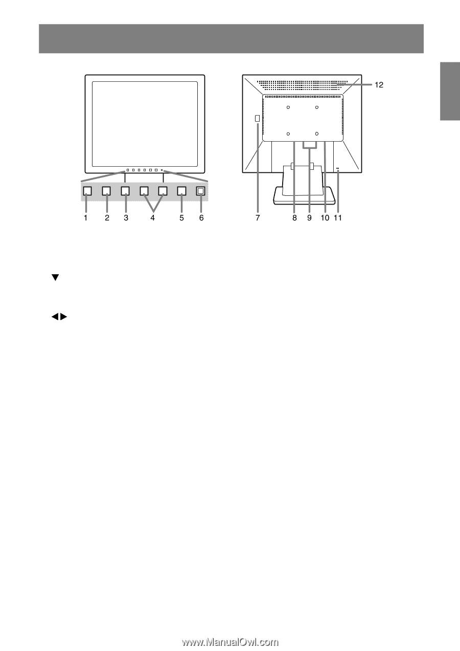
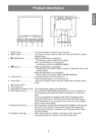
Product description English Español Italiano Français Deutsch English 1. INPUT button To switch between the signal's input terminals. 2. MENU button This button is used to pop-up, select and close the OSD (On Screen Display) Menu. 3. / MODE button When the OSD Menu is displayed: This button is used to select menu options. When the OSD Menu is not displayed: This button is used to set DISPLAY MODE. 4. buttons When the OSD Menu is displayed: These buttons are used to select an option or adjust the value of the selected option. When the OSD Menu is not displayed: These buttons are used to adjust backlight brightness. 5. Power button Pressing this button turns the power on. Press the button again to turn the power off. 6. Power LED This LED is lit green when in use and orange when in power-saving mode. 7. Main power switch 8. Power terminal 9. Analog RGB input terminal 1 and 2 ... The analog signal cable is connected here. 10. DVI-D input terminal The computer's digital RGB output terminal can be connected here. The separately-sold cable (NL-C01E) is necessary for connection. (p.8) It can be connected to a computer with a DVI-compatible output terminal (DVI-D24 pin or DVI-I29 pin) and which has SXGA output ability. Depending on the computer to be connected, correct display may or may not be possible. 11. Security lock anchor By connecting a security lock (commercially available) to the security lock anchor, the monitor is fixed so that it cannot be transported. The security slot works in conjunction with Kensington Micro Saver Security Systems. 12. Ventilation openings Note: Never block the ventilation openings as this may lead to overheating inside the monitor and result in malfunction. 9
-
 1
1 -
2
-
3
-
 4
4 -
 5
5 -
 6
6 -
 7
7 -
 8
8 -
 9
9 -
 10
10 -
 11
11 -
 12
12 -
 13
13 -
 14
14 -
15
-
16
-
17
-
18
-
19
-
20
-
21
-
22
-
23
-
24
-
25
-
26
-
27
-
28
-
29
-
30
-
31
-
32
-
33
-
34
-
35
-
36
-
37
-
38
-
39
-
40
-
41
-
42
-
43
-
44
-
45
-
46
-
47
-
48
-
49
-
50
-
51
-
52
-
53
-
54
-
55
-
56
-
57
-
58
-
59
-
60
-
61
-
62
-
63
-
64
-
65
-
66
-
67
-
68
-
69
-
70
-
71
-
72
-
73
-
74
-
75
-
76
-
77
-
78
-
79
-
80
-
81
-
82
-
83
-
84
-
85
-
86
-
87
-
88
-
89
-
90
-
91
-
92
-
93
-
94
-
95
-
96
-
97
-
98
-
99
-
100
-
101
-
102
-
103
-
104
-
105
-
106
-
107
-
108
-
109
-
110
-
111
-
112
-
113
-
114
-
115
-
116
-
117
-
118
-
119
-
120
-
121
-
122
-
123
-
124
-
125
-
126
-
127
-
128
-
129
-
130
-
131
-
132
 |
 |