Sharp XG-PH70X XG-PH70X Operation Manual - Page 17
Projector Side View, Numbers
 |
UPC - 074000365117
View all Sharp XG-PH70X manuals
Add to My Manuals
Save this manual to your list of manuals |
Page 17 highlights
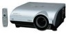
Introduction Numbers in refer to the main pages in this operation manual where the topic is explained. Projector (Side View) Terminals Refer to "INPUT/OUTPUT Terminals and Connectable Main Equipment" on page 24. INPUT 1 terminal 27 Terminal for computer RGB and component signals. AUDIO input (1) terminal 27 Audio input terminal for INPUT 1. INPUT 2 terminals 28 BNC terminals for computer RGB and component signals. RS-232C terminal 35 Terminal for controlling the projector using a computer. INPUT 4 terminal 34 Terminal for connecting video equipment. AUDIO input (4, 5) terminals 34 Shared audio input terminals for INPUT 4 and 5. INPUT 5 terminal 34 Terminal for connecting video equipment with an S-video terminal. WIRED REMOTE terminal 18 For connecting the remote control to the projector when the signals from the remote control cannot reach the remote control sensor. 29 INPUT 3 terminal Terminal for DVI digital RGB and digital component signals. 36 OUTPUT (FOR INPUT 1, 2) terminal Output terminal for computer RGB and component signals. Shared for INPUT 1 and 2. 28 AUDIO input (2, 3) terminal Shared audio input terminal for INPUT 2 and 3. 36 AUDIO OUTPUT terminal Audio output terminal shared for INPUT 1-5. 35 LAN terminal Terminal for controlling the projector using a computer via network. 37 AC socket Connect the supplied Power cord. 17 Remote control sensor Kensington Security Standard connector 93 Exhaust vent The speed and pitch of the cooling fan may change during operation in response to internal temperature changes. This is normal operation and does not indicate a malfunction. Using the Kensington Lock • This projector has a Kensington Security Standard connector for use with a Kensington MicroSaver Security System. Refer to the information that came with the system for instructions on how to use it to secure the projector. -15
-
 1
1 -
2
-
3
-
4
-
5
-
6
-
7
-
8
-
9
-
10
-
11
-
 12
12 -
 13
13 -
 14
14 -
 15
15 -
 16
16 -
 17
17 -
 18
18 -
 19
19 -
 20
20 -
 21
21 -
 22
22 -
23
-
24
-
25
-
26
-
27
-
28
-
29
-
30
-
31
-
32
-
33
-
34
-
35
-
36
-
37
-
38
-
39
-
40
-
41
-
42
-
43
-
44
-
45
-
46
-
47
-
48
-
49
-
50
-
51
-
52
-
53
-
54
-
55
-
56
-
57
-
58
-
59
-
60
-
61
-
62
-
63
-
64
-
65
-
66
-
67
-
68
-
69
-
70
-
71
-
72
-
73
-
74
-
75
-
76
-
77
-
78
-
79
-
80
-
81
-
82
-
83
-
84
-
85
-
86
-
87
-
88
-
89
-
90
-
91
-
92
-
93
-
94
-
95
-
96
-
97
-
98
-
99
-
100
-
101
-
102
-
103
-
104
-
105
-
106
-
107
-
108
-
109
-
110
 |
 |
