Sony DSR 25 Operating Instructions - Page 19
IL4415 A, VMC-IL4615 A. Use when a device, INPUT connectors, AUDIO INPUT LEVEL -10/-2/+4 selector - dvcam manual
 |
UPC - 027242604001
View all Sony DSR 25 manuals
Add to My Manuals
Save this manual to your list of manuals |
Page 19 highlights
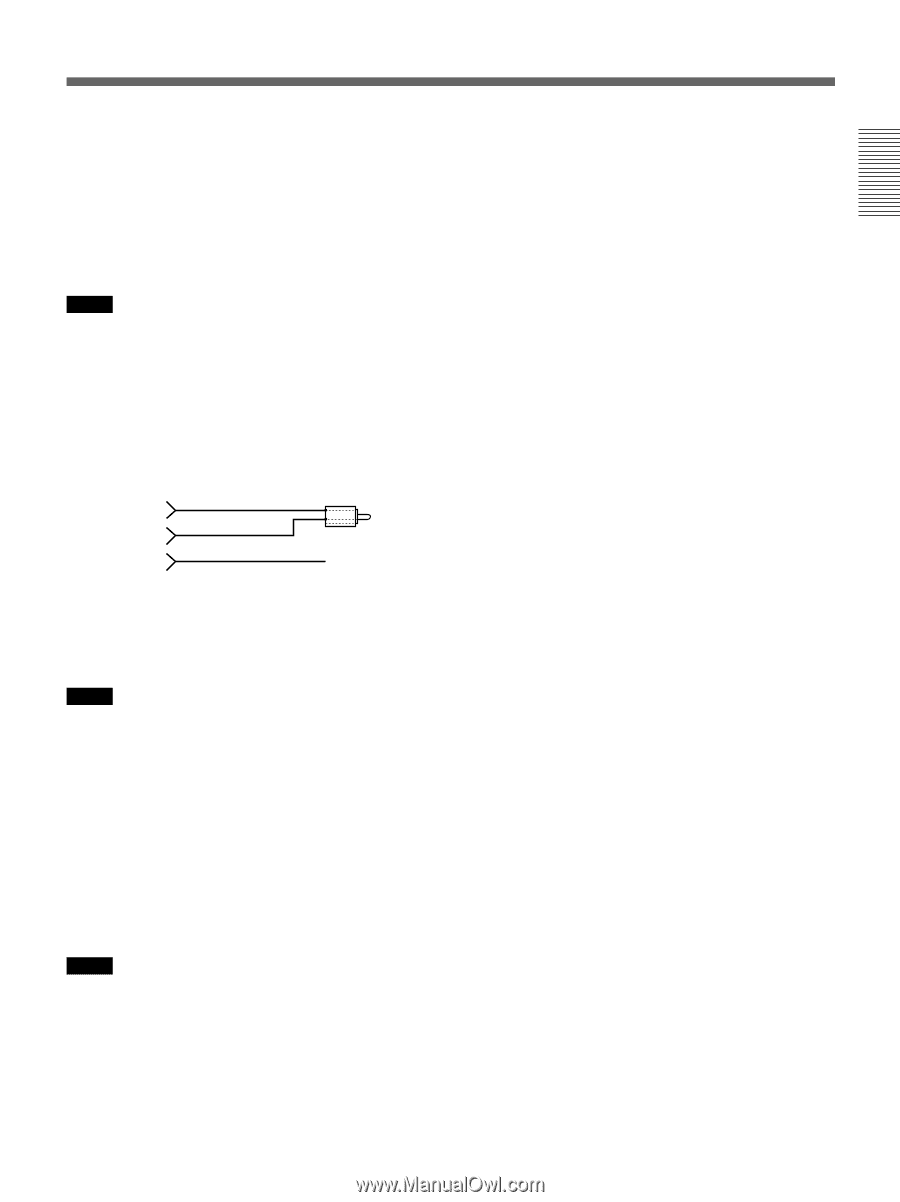
Chapter 1 Overview 2 INPUT connectors Use to input analog video and audio signals. To connect a device equipped with S-video output, use the S VIDEO connector on the unit. During normal recording, sounds are recorded onto channels 1 and 2; they cannot be recorded onto channels 3 and 4. During audio dubbing, sounds are dubbed onto channels 3 and 4. Notes • In the audio dubbing mode, the AUDIO (CH-1/3) jack functions as channel 3 input and the AUDIO (CH-2/4) jack functions as channel 4 input. • To input balanced audio signals via AUDIO jacks, use a conversion cable as shown below. (The COLD side is open.) For details on conversion cables, refer to the instruction manual of the devices you use. GND HOT COLD × 3 AUDIO INPUT LEVEL (-10/-2/+4) selector Selects one from among -10 dB, -2 dB, or +4 dB according to the audio level of the signal input via the AUDIO jacks in INPUT. Notes • If this selector setting is not appropriate, clipping distortion or noise may occur. • For more information on the setting of this selector, see "When you set the AUDIO INPUT LEVEL selector" on page 71 (GB). 4 NTSC/PAL select switch Used to switch the color system of signals that will be recorded on the unit when you use analog input. Before inputting NTSC or PAL formatted analog video signals, set this switch to the appropriate position according to the color system of the signal input. Notes • If the color system of the input signals is different from that of the switch setting, picture will be blanked. • While signals are input to the DV jack or during playback, this switch setting is invalid. The unit detects the color system of the signals automatically. • When this switch is set to PAL, the unit works as a PAL model. Therefore, the time code generated by the unit during recording in the DVCAM format is that of the non-drop frame mode. Even if an NTSC formatted signal is input to the DV jack, the time code generated by the unit is non-drop frame mode as long as the switch is set to PAL, regardless of the TC FORMAT setting on the TC/UB SET menu. If you intend to set the unit to generate the time code in the drop frame mode, set this switch to NTSC. • The color system of the signals output from the unit is the one recorded on the tape being played back. The unit cannot convert the color system of signals of one system into that of the other. (For example: converting NTSC formatted signals into PAL formatted signals is not possible) Therefore, to view or record the signal output from the unit, you need a device compatible with the color system of the signals output from the unit. • When the color system of playback signals is different from the one last used on the unit, playback picture and sound will be distorted and time code will be discontinuous for a short time at the beginning of the playback. • If you play back a tape with both NTSC and PAL color system recordings, the following limitations are applied. - At the point where the color system of the recorded signals changes, the picture may be distorted or audio noise may be output. - The tape transport control buttons may be disabled until the tape running is stabilized. • Do not change this switch setting during recording. • At the beginning or end of playback, if the color system of signals recorded on the tape used is different from this switch setting, pictures and sounds output from the unit, and pictures on the LCD monitor, etc., may be distorted. 5 DV jack (4-pin) Used to input/output the digital signal that complies with the i.LINK standard (Recommended cable: VMCIL4415 (A), VMC-IL4615 (A)). Use when a device connected to the unit has a DV jack. If you connect the unit and another device using DV jacks, you can minimize deterioration of picture quality during recording, dubbing, or capturing still pictures, all by means of digital signal processing. For details, refer to the instruction manual of the external device. (Continued) 19 Chapter 1 Overview (GB)
-
 1
1 -
2
-
3
-
4
-
5
-
6
-
7
-
8
-
9
-
10
-
11
-
12
-
13
-
 14
14 -
 15
15 -
 16
16 -
 17
17 -
 18
18 -
 19
19 -
 20
20 -
 21
21 -
 22
22 -
 23
23 -
 24
24 -
25
-
26
-
27
-
28
-
29
-
30
-
31
-
32
-
33
-
34
-
35
-
36
-
37
-
38
-
39
-
40
-
41
-
42
-
43
-
44
-
45
-
46
-
47
-
48
-
49
-
50
-
51
-
52
-
53
-
54
-
55
-
56
-
57
-
58
-
59
-
60
-
61
-
62
-
63
-
64
-
65
-
66
-
67
-
68
-
69
-
70
-
71
-
72
-
73
-
74
-
75
-
76
-
77
-
78
-
79
-
80
-
81
-
82
-
83
-
84
-
85
-
86
-
87
-
88
-
89
-
90
-
91
-
92
-
93
-
94
-
95
-
96
-
97
-
98
-
99
-
100
-
101
-
102
-
103
-
104
-
105
-
106
-
107
-
108
-
109
-
110
-
111
-
112
-
113
-
114
-
115
-
116
-
117
-
118
-
119
-
120
-
121
-
122
-
123
-
124
-
125
-
126
-
127
-
128
-
129
-
130
-
131
-
132
-
133
-
134
-
135
-
136
-
137
-
138
-
139
-
140
-
141
-
142
-
143
-
144
-
145
-
146
-
147
-
148
-
149
-
150
-
151
-
152
-
153
-
154
-
155
-
156
-
157
-
158
-
159
-
160
-
161
-
162
-
163
-
164
-
165
-
166
-
167
-
168
 |
 |