Sony DVO1000MD User Manual (Instructions For Use) - Page 13
Location and Function of Parts, Front Panel
 |
View all Sony DVO1000MD manuals
Add to My Manuals
Save this manual to your list of manuals |
Page 13 highlights
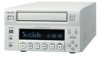
Overview Location and Function of Parts Front Panel 1 1 (on/standby) switch and indicator 2 Disc tray 3 OPEN/CLOSE button 6 Front panel display 5 REMOTE 2 connector 4 REMOTE 1 connector 7 Disc control section 8 Menu/disc control section 1 1 (on/standby) switch and indicator Press to power on the unit when the MAIN POWER switch (see page 16) on the rear panel is turned on. This causes the front panel display to light. Even if the unit is in standby mode, the indicator is lit in green when the MAIN POWER switch is set to on. To set the unit to standby mode, press this switch again. Note If the MAIN POWER switch on the rear panel is not set to on, the unit will not turn on even if you press the 1 (on/standby) switch. 2 Disc tray Used to insert or remove the disc. 3 OPEN/CLOSE button Press to open or close the disc tray. 4 REMOTE 1 connector (stereo mini jack) Connect a SVRM-100A remote control unit (not supplied) to this connector for remote control. 5 REMOTE 2 connector (mini jack) Connect a foot switch (not supplied) to this connector. You can control recording and pausing using this foot switch. 13 Location and Function of Parts
-
 1
1 -
2
-
3
-
4
-
5
-
6
-
7
-
 8
8 -
 9
9 -
 10
10 -
 11
11 -
 12
12 -
 13
13 -
 14
14 -
 15
15 -
 16
16 -
 17
17 -
 18
18 -
19
-
20
-
21
-
22
-
23
-
24
-
25
-
26
-
27
-
28
-
29
-
30
-
31
-
32
-
33
-
34
-
35
-
36
-
37
-
38
-
39
-
40
-
41
-
42
-
43
-
44
-
45
-
46
-
47
-
48
-
49
-
50
-
51
-
52
-
53
-
54
-
55
-
56
-
57
-
58
-
59
-
60
-
61
-
62
-
63
-
64
-
65
-
66
-
67
-
68
-
69
 |
 |
