Sony EVID70/W Product Brochure (rmbr300) - Page 25
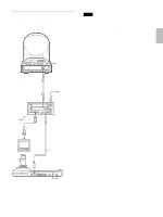
Set to ON for RS-422, or OFF for RS-232C., Connect to the VISCA RS-232C IN connector - evi d70p
 |
View all Sony EVID70/W manuals
Add to My Manuals
Save this manual to your list of manuals |
Page 25 highlights
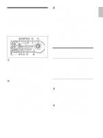
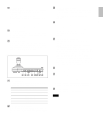
Overview R POWER button Press this button to light the CAMERA button(s) corresponding to the status of the connected camera(s). Blue: The power of the camera is on. Yellow green: The camera is in standby mode. Off: No camera is connected. Hold down this button and press CAMERA button 1 to 7 to turn on/off the power of the camera corresponding to the pressed button. S CAMERA buttons Press one of the buttons to select the camera from among those connected. The selected CAMERA button lights in blue. T POSITION buttons You can store various camera settings such as the pan, tilt and zoom positions to the memory of the camera corresponding to each POSITION button, and load the settings in the memory. Rear/Bottom MODE RS-232C VISCA RS-422 TALLY/CONTACT ! CONTACT(TALLY) TALLY 1 9 1 9 CONTACT DC IN 12V ON/OFF wa ws wd wf wg wh wj wk U MODE selector Select the position corresponding to the VISCAcontrollable camera to be connected. Switch position 0 1 2 3 4 Camera mode Automatically selected (default) BRC-300/300P EVI-D70/D70P EVI-D100/D100P EVI-D30/D30P V VISCA RS-232C connector Connect to the VISCA RS-232C IN connector of the camera or the BRU-300/300P Optical Multiplex Unit. W VISCA RS-422 connector Connect to the VISCA RS-422 connector of the camera or the BRU-300/300P Optical Multiplex Unit. An RS-422 connector plug is attached at the factory. X TALLY/CONTACT connector This connector is used for the tally lamp input or the contact output. Select the function of the connector using the TALLY/CONTACT selector. An RS-422 connector plug is attached at the factory. Y TALLY/CONTACT selector Select the function of the TALLY/CONTACT connector. TALLY: The tally lamp of the camera selected with the connected switcher lights. CONTACT: The contact output corresponding to the camera address selected with this unit is shortcircuited against the connected switcher. CONTACT (TALLY): The contact output corresponding to the camera address selected with this unit is short-circuited against the connected switcher and the tally lamp of the camera selected with the connected switcher lights. wh DC IN 12V connector Connect the supplied AC power adaptor. wj DIP switches (bottom) Switch 1 (RS-232C/RS-422 selector) Set to ON for RS-422, or OFF for RS-232C. Switch 2 (Communication baud rate selector) Set to ON for 38400bps, or OFF for 9600bps. wk ON/OFF switch Press this switch to turn on/off this unit. Note Set the switches before you turn on the power of this unit. Otherwise, the setting is not effective. 7 Location and Function of Parts GB
-
 1
1 -
2
-
3
-
4
-
5
-
6
-
7
-
8
-
9
-
10
-
11
-
12
-
13
-
14
-
15
-
16
-
17
-
18
-
19
-
 20
20 -
 21
21 -
 22
22 -
 23
23 -
 24
24 -
 25
25 -
 26
26 -
 27
27 -
 28
28 -
 29
29 -
 30
30 -
31
-
32
-
33
-
34
-
35
-
36
-
37
-
38
-
39
-
40
-
41
-
42
-
43
-
44
-
45
-
46
-
47
-
48
-
49
-
50
-
51
-
52
-
53
-
54
-
55
-
56
-
57
-
58
-
59
-
60
-
61
-
62
-
63
-
64
-
65
-
66
-
67
-
68
-
69
-
70
-
71
-
72
-
73
-
74
-
75
-
76
-
77
-
78
-
79
-
80
-
81
-
82
-
83
-
84
-
85
-
86
-
87
-
88
-
89
-
90
-
91
-
92
 |
 |
