Sony FCBEH3300 Product Manual (Tehnical Manual for new HD Block Cameras) - Page 19
Motion Detection Function, Features, Frames
 |
View all Sony FCBEH3300 manuals
Add to My Manuals
Save this manual to your list of manuals |
Page 19 highlights
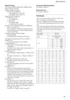
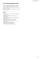
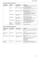
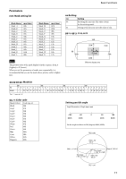
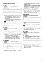
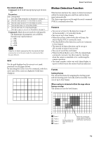
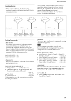
Basic Functions Non Interlock Mask Command: 8x 01 04 6F mm 0p 0p 0q 0q 0r 0r 0s 0s FF Parameters: mm Setting Mask See "mm: Mask setting list" in "Parameters" on page 17. pp Sets the center position "x" of the Mask on screen. qq Sets the center position "y" of the Mask on screen. rr Sets the half value "w" of the Mask Width. ss Sets the half value "h" of the Mask Height. See "pp: x, qq: y, rr: w, ss: h" in "Parameters" on page 17. Commands: Mask does not interlock with pan/tilt. The limitations of parameters are as follows. (hexadecimal representation) x: ±50h w: ±50h y: ±2Dh h: ±2Dh Note When the Set Mask command and the Non Interlock Mask command are set to the same mask, the command set later becomes effective. Grid Use the grid displayed on the screen to set mask positions (see the figure below). By executing the Center Line On command, only the x and y axes of the center are displayed. Grids lines disappear. Motion Detection Function This function instructs the camera to detect movement within the monitoring area and then send an alarm signal automatically. The Detect signal goes out through the serial command (VISCA) communication line. Features • You can set a frame for the detection range of 16 (horizontally) × 8 (vertically) blocks. • You can set up to four frames. • When the motion is detected in the set frame, the Alarm Replay VISCA command is sent. • The threshold level for detection can be set (common to four frames). • The interval of alarm detection can be set up to 255 seconds in units of one second. • You can set on/off for each frame. • When the Block Mode is set to ON, the Alarm Reply command is not sent. Use this mode for checking when the camera is installed or for confirming the camera operation. • The frame number is also sent with Alarm Replay to report in which frame the motion has been detected. Frames Setting frames You can set the frame by assigning the starting point and terminating point vertically and horizontally. You can set up to four frames. When motion is detected within the rage where frames overlap The alarms are sent for both frames. Frame 1 Frame 2 Frame 3 Frame 4 At this position, the alarm for frame 3 is sent. Within this overlapped range, alarms are sent for both frame 3 and frame 4. 19
-
 1
1 -
2
-
3
-
4
-
5
-
6
-
7
-
8
-
9
-
10
-
11
-
12
-
13
-
 14
14 -
 15
15 -
 16
16 -
 17
17 -
 18
18 -
 19
19 -
 20
20 -
 21
21 -
 22
22 -
 23
23 -
 24
24 -
25
-
26
-
27
-
28
-
29
-
30
-
31
-
32
-
33
-
34
-
35
-
36
-
37
-
38
-
39
-
40
-
41
-
42
-
43
-
44
-
45
-
46
-
47
-
48
-
49
-
50
-
51
-
52
-
53
-
54
-
55
-
56
-
57
-
58
-
59
-
60
-
61
-
62
-
63
-
64
 |
 |