Sony HCD-C700 Operating Instructions - Page 23
Step 3: TV and Video Component Hookups
 |
View all Sony HCD-C700 manuals
Add to My Manuals
Save this manual to your list of manuals |
Page 23 highlights
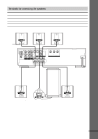
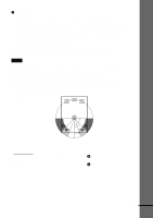
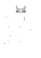
Getting Started Step 3: TV and Video Component Hookups Required cords Video cord for connecting a TV monitor Yellow Yellow Audio/video cords (not supplied) When connecting a cord, be sure to match the colour-coded pins to the appropriate jacks on the components. Yellow (Video) White (L/audio) Red (R/audio) Yellow (Video) White (L/audio) Red (R/audio) Jacks for connecting video components Connect a TV monitor VCR Digital satellite receiver To the MONITOR OUT jack VIDEO 1 jacks VIDEO 2 jacks z When using the S-video jack instead of the video jacks Your TV monitor must also be connected via an S-video jack. S-video signals are on a separate bus from the video signals and will not be output through the video jacks. z When you are connecting the monitor, projector, or AV amplifier (receiver) having component video input jacks (Y, PB, PR) Connect the component via the COMPONENT VIDEO OUT jacks using a component video cord (not supplied) or three video cords (not supplied) of the same kind and length. You will enjoy accurate colour reproduction and high quality images. Notes • When you select VIDEO 1 using the FUNCTION button, the signal is output from the front L/R speakers, but not from the VIDEO 1 VIDEO OUT and AUDIO OUT L/R jacks. • When you use the Video 1 line outputs, please set the unit to 2CH STEREO mode. If the unit is not in 2CH STEREO mode, the line outputs may not function properly. continued 23
-
 1
1 -
2
-
3
-
4
-
5
-
6
-
7
-
8
-
9
-
10
-
11
-
12
-
13
-
14
-
15
-
16
-
17
-
 18
18 -
 19
19 -
 20
20 -
 21
21 -
 22
22 -
 23
23 -
 24
24 -
 25
25 -
 26
26 -
 27
27 -
 28
28 -
29
-
30
-
31
-
32
-
33
-
34
-
35
-
36
-
37
-
38
-
39
-
40
-
41
-
42
-
43
-
44
-
45
-
46
-
47
-
48
-
49
-
50
-
51
-
52
-
53
-
54
-
55
-
56
-
57
-
58
-
59
-
60
-
61
-
62
-
63
-
64
-
65
-
66
-
67
-
68
-
69
-
70
-
71
-
72
-
73
-
74
-
75
-
76
-
77
-
78
-
79
-
80
-
81
-
82
-
83
-
84
 |
 |
