Sony KLV-30XBR900 Operating Instructions - Page 20
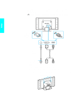
Media receiver unit Rear Panel, SUB WOOFER OUT - media box
 |
UPC - 027242619630
View all Sony KLV-30XBR900 manuals
Add to My Manuals
Save this manual to your list of manuals |
Page 20 highlights
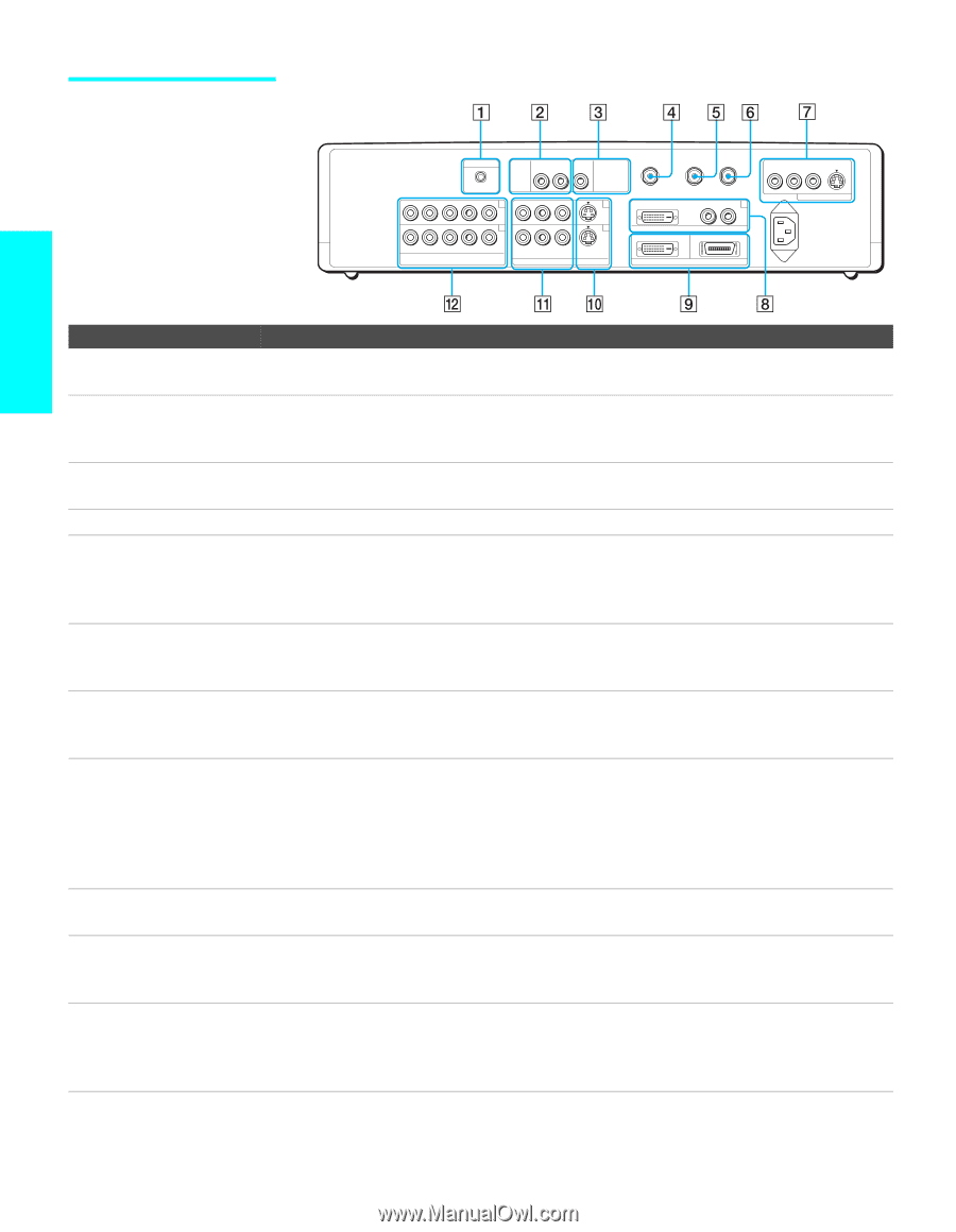
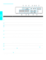
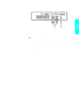
Media receiver unit Rear Panel AUDIO IN CONTROL S OUT AV MOUSE 4 AUDIO OUT (VAR/FIX) R-AUDIO-L SUBWOOFER OUT (VAR) VHF/UHF TO CONVERTER AUX 1 DVI-HDTV R-AUDIO-L 6 5 3 R-AUDIO-L Y PB PR HD/DVD IN ( 1080i / 720p / 480p / 480i ) R-AUDIO-L VIDEO S VIDEO VIDEO IN DVI-HDTV IN WHITE BLACK DISPLAY SIGNAL OUT R-AUDIO-L VIDEO S VIDEO MONITOR OUT ~ AC IN Setup Jack Description 1 CONTROL S OUT Allows the TV to send remote control signals to other Sony infrared-controlled audio or video equipment that has the CONTROL S function. 2 AUDIO OUT (VAR/FIX) R-AUDIO-L Connects to the left and right audio input jacks of your audio or video equipment. You can use these outputs to listen to your TV's audio through your stereo system. 3 SUB WOOFER OUT Connects to the input jack of your sub woofer. (VAR) 4 VHF/UHF Primary RF input that connects to your VHF/UHF antenna or cable. 5 TO CONVERTER Connects to your cable box input jack. This VHF/UHF output jack lets you set up your TV to switch between scrambled channels (coming through a cable box) and unscrambled cable channels. Use this jack instead of a splitter to get better picture quality when you need to switch between scrambled and unscrambled cable channels. For details, see pages 24 and 25. 6 AUX Auxiliary RF input that connects to your antenna, CATV cable, or cable box output jack. This is convenient if you are using two VHF/UHF sources (antenna, CATV cable, or cable box). For details, see pages 24 and 25. 7 MONITOR OUT S VIDEO/VIDEO/ R-AUDIO-L Lets you record the program you are watching to a VCR. When two VCRs are connected, you can use the TV as a monitor for tape-to-tape editing (not available with 480p, 720p, or 1080i when the input is set to VIDEO 4-6). 8 DVI-HDTV IN DVI-HDTV/ R-AUDIO-L (VIDEO IN 6) Can accommodate a copy-protected digital connection (HDCP*) to other devices (such as digital set-top boxes) that have compatible interfaces. The DVI-HDTV input terminal is compliant with the EIA-861 standard and is not intended for use with personal computers. See the instruction manual that came with your equipment for details about connecting and using it with the TV. Use a DVI-D single link cable. 9 DISPLAY SIGNAL Connects to the display input jack of the display unit by using the supplied display interface OUT cable. 0 S VIDEO (VIDEO IN 1/3) Connects to the S VIDEO OUT jack of your VCR or other video equipment that has S VIDEO. S VIDEO provides better picture quality than either composite video (qa) or VHF/UHF (4) connections. qa VIDEO/R-AUDIO-L (VIDEO IN 1/3) Connect to the composite A/V output jacks on your VCR or other video component. A third component A/V input jack (VIDEO 2 INPUT) is located on the front panel of the Media receiver unit. These video connections provide better picture quality than the VHF/UHF (4) connections. * High-bandwidth Digital Content Protection 18
-
 1
1 -
2
-
3
-
4
-
5
-
6
-
7
-
8
-
9
-
10
-
11
-
12
-
13
-
14
-
 15
15 -
 16
16 -
 17
17 -
 18
18 -
 19
19 -
 20
20 -
 21
21 -
 22
22 -
 23
23 -
 24
24 -
 25
25 -
26
-
27
-
28
-
29
-
30
-
31
-
32
-
33
-
34
-
35
-
36
-
37
-
38
-
39
-
40
-
41
-
42
-
43
-
44
-
45
-
46
-
47
-
48
-
49
-
50
-
51
-
52
-
53
-
54
-
55
-
56
-
57
-
58
-
59
-
60
-
61
-
62
-
63
-
64
-
65
-
66
-
67
-
68
-
69
-
70
-
71
-
72
-
73
-
74
-
75
-
76
-
77
-
78
-
79
-
80
-
81
-
82
-
83
-
84
-
85
-
86
-
87
-
88
-
89
-
90
-
91
-
92
-
93
-
94
-
95
-
96
-
97
-
98
-
99
-
100
-
101
-
102
-
103
-
104
-
105
-
106
-
107
-
108
-
109
-
110
-
111
-
112
 |
 |