Sony KLV-30XBR900 Operating Instructions - Page 23
media receiver unit's AC IN jack., After making all connections
 |
UPC - 027242619630
View all Sony KLV-30XBR900 manuals
Add to My Manuals
Save this manual to your list of manuals |
Page 23 highlights
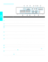
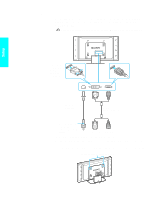
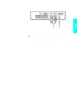
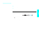
Setup 3 Connect the other end of display interface cable to the Media receiver unit's DISPLAY SIGNAL OUT jack, and connect the AC power cord (supplied) to the media receiver unit's AC IN jack. AUDIO IN CONTROL S OUT AV MOUSE 4 AUDIO OUT (VAR/FIX) R-AUDIO-L SUBWOOFER OUT (VAR) VHF/UHF TO CONVERTER AUX 1 DVI-HDTV R-AUDIO-L 6 5 3 R-AUDIO-L Y PB PR HD/DVD IN ( 1080i / 720p / 480p / 480i ) R-AUDIO-L VIDEO S VIDEO VIDEO IN DVI-HDTV IN WHITE BLACK DISPLAY SIGNAL OUT Tighten the screw slowly until the screw is stabilized. R-AUDIO-L VIDEO S VIDEO MONITOR OUT ~ AC IN Display interface AC power cord cable (supplied) (supplied) 4 After making all connections, connect the AC power cords (supplied) to wall outlets. Be sure to use the supplied AC power cords. When connecting optional components, do not connect the AC power cords to wall outlets until you have completed making all connections. Do not tighten the screws too much. It may damage the screws. Handle the display interface cable with care. If you pull the cable by catching your feet on the cable, this unit may fall and cause injury. Do not use damaged cables, such as cables whose connectors are deformed. 21
-
 1
1 -
2
-
3
-
4
-
5
-
6
-
7
-
8
-
9
-
10
-
11
-
12
-
13
-
14
-
15
-
16
-
17
-
 18
18 -
 19
19 -
 20
20 -
 21
21 -
 22
22 -
 23
23 -
 24
24 -
 25
25 -
 26
26 -
 27
27 -
 28
28 -
29
-
30
-
31
-
32
-
33
-
34
-
35
-
36
-
37
-
38
-
39
-
40
-
41
-
42
-
43
-
44
-
45
-
46
-
47
-
48
-
49
-
50
-
51
-
52
-
53
-
54
-
55
-
56
-
57
-
58
-
59
-
60
-
61
-
62
-
63
-
64
-
65
-
66
-
67
-
68
-
69
-
70
-
71
-
72
-
73
-
74
-
75
-
76
-
77
-
78
-
79
-
80
-
81
-
82
-
83
-
84
-
85
-
86
-
87
-
88
-
89
-
90
-
91
-
92
-
93
-
94
-
95
-
96
-
97
-
98
-
99
-
100
-
101
-
102
-
103
-
104
-
105
-
106
-
107
-
108
-
109
-
110
-
111
-
112
 |
 |
