Sony KV-1981R Primary User Manual - Page 4
Set-up, Operation
 |
View all Sony KV-1981R manuals
Add to My Manuals
Save this manual to your list of manuals |
Page 4 highlights
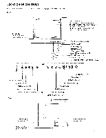
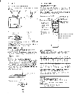
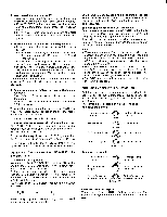
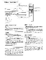
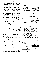
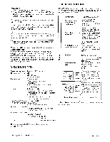
-SET-UP . INDOOR ANTENNA ADJUSTMENT For VHF/UHF reception, use the telescopic dipole antenna. Rear of TV, N Fasten with a screwdriver. VHF/UHF OPERATION VIEWING TV PROGRAMS This TV set is capable of receiving normal VHF and UHF broadcasts plus cable TV channels. (See "Cable TV channel chart" below.) Usually the Remote Commander is all that is needed to operate the TV set in everyday use. Remote Commander RM•728 TV/VIDEO button MUTING button SLEEP button Channel number buttons DISPLAY button ENTER button Buttons which are not duplicated on the TV 1O O CI O =I O POWER switch MTS (Multichannel TV Sound) button CH (channel) scan buttons VOL (volume) buttons PICTURE buttons The indoor telescopic dipole antenna will provide good reception in most areas. Adjust the length, direction and angle of both elements symmetrically until the picture is clearest. REMOTE COMMANDER 1 Turn the Remote Commander face down, press the tab and lift the cover. 2 Place batteries in the.Commander with the polarities in the correct directions, as illustrated inside the case. 3 Replace the cover. Notes • Use 2 size AA batteries (IEC designation R6). • In normal operation, batteries will last up to half a year. If the set does not operate properly, the batteries might be exhausted. Replace all with new ones. • To avoid damage from possible battery leakage, remove the batteries for extended unused periods. • Be sure that there are no obstructions between the Commander and the TV. • Operable range is limited. I jgo[2:3CDCT-- Remote control detector Operable range 4 7 me ters (23 feet) 30* 0 0 000 000 0 GI 0 000 000 OQO Cable TV channel chart* Cable TV systems use letters or numbers to designate channels. To tune in a channel, refer to this chart. Number on this TV Corresponding CATV channel 1 5 6 14 15 16 17 A-8 A-7 A-6 A B C D 18 19 20 21 22 23 24 25 26 27 28 29 30 E FGH I J K LMNO PQ 31 32 33 34 35 36 37 38 39 R S T U V W W+1 W+2 W+3 93 94 W*57 W+58 95 96 97 98 99 100 101 102 A-5 A-4 A-3 A-2 A-1 W+59 W, 60 W+61 123 124 125 W+82 W+83 WI-84 Check with your local cable TV company for more complete information on the available channels. *The designation of the cable TV channels conforms to the EIA/NCTA recommended standards. Preparation Make sure the following are properly set. • The VIDEO/EXT-AUDIO selector should be set to VIDEO. • The AUTO STEREO switch should be set to ON. • Cable switch For VHF and UHF channels, set to OFF. For cable TV channels, set to ON.
-
 1
1 -
 2
2 -
 3
3 -
 4
4 -
 5
5 -
 6
6 -
 7
7 -
 8
8
 |
 |
