Sony MDS-JB940 Operating Instructions - Page 9
Rear panel description, Press DISPLAY/CHAR or DISPLAY repeatedly
 |
View all Sony MDS-JB940 manuals
Add to My Manuals
Save this manual to your list of manuals |
Page 9 highlights
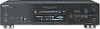
Location and Function of Controls • "OPT2" lights when the program source is connected to the DIGITAL OPTICAL IN2 connector. • "COAX" lights when the program source is connected to the DIGITAL COAXIAL IN jack. • "ANALOG" lights when the program source is connected to the ANALOG IN jacks. F Music calender Shows all the track numbers within a grid if the MD is a premastered disc, or without a grid if the MD is a recordable disc. If the total number of tracks exceeds 15, B appears to the right of number 15 in the music calendar. G SLEEP indicator (41) Lights when the deck is set to turn off automatically after specified minutes. H Level meters Display the audio signal levels during playing and recording. Note The display format that you have selected in each of the deck statuses (play, recording, etc.) will appear whenever the deck enters that status and you press DISPLAY/CHAR (or DISPLAY) or TIME until you change the format to another (see the following sections for details). If you disconnect the AC power cord, however, all the displays will revert to their default (i.e., the factory set display) the next time you turn on the deck. To change the display in stop mode Press DISPLAY/CHAR (or DISPLAY) repeatedly to change the display. Each press of the button changes the display as follows: Total number of tracks, total recorded time and disc name1) r The contents of a program (only when "PGM" lights up) r Level of the input signal (setting value of the recording level) r Pitch display r DF (digital filter) display 1) "No Name" appears when the disc has no name. Rear panel description COI OIC COI OIC I I2 I1 O O A ANALOG IN jacks (11) (14) Use to input analog signals from other components. B ANALOG OUT jacks (11) Use to output analog signals to other components. C CONTROL A1ΙΙ jacks (11) (44) D DIGITAL COAXIAL IN jack (11) (14) Connect a digital coaxial cable to input digital signals from other components. E DIGITAL OPTICAL IN connectors (11) (14) Connect a digital optical cable to input digital signals from other components. There is no distinction of IN1 and IN2 connectors. F DIGITAL COAXIAL OUT jack (11) Connect a digital coaxial cable to output digital signals to other components. G DIGITAL OPTICAL OUT connector (11) Connect a digital optical cable to output digital signals to other components. 9 Display window description/Rear panel description GB
-
 1
1 -
2
-
3
-
 4
4 -
 5
5 -
 6
6 -
 7
7 -
 8
8 -
 9
9 -
 10
10 -
 11
11 -
 12
12 -
 13
13 -
 14
14 -
15
-
16
-
17
-
18
-
19
-
20
-
21
-
22
-
23
-
24
-
25
-
26
-
27
-
28
-
29
-
30
-
31
-
32
-
33
-
34
-
35
-
36
-
37
-
38
-
39
-
40
-
41
-
42
-
43
-
44
-
45
-
46
-
47
-
48
-
49
-
50
-
51
-
52
-
53
-
54
-
55
-
56
-
57
-
58
-
59
-
60
-
61
-
62
-
63
-
64
-
65
-
66
-
67
-
68
-
69
-
70
-
71
-
72
-
73
-
74
-
75
-
76
-
77
-
78
-
79
-
80
-
81
-
82
-
83
-
84
-
85
-
86
-
87
-
88
-
89
-
90
-
91
-
92
-
93
-
94
-
95
-
96
-
97
-
98
-
99
-
100
-
101
-
102
-
103
-
104
-
105
-
106
-
107
-
108
-
109
-
110
-
111
-
112
-
113
-
114
-
115
-
116
-
117
-
118
-
119
-
120
 |
 |
