Sony MHC-GX450 MHCGX450 Instructions (tuner portion of Stereo System) - Page 30
Transmitter, (MHC-GX750 only) - stereo system
 |
View all Sony MHC-GX450 manuals
Add to My Manuals
Save this manual to your list of manuals |
Page 30 highlights
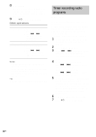
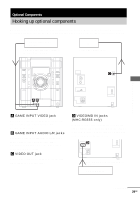
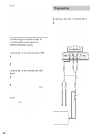
Notes • The video game machine image may appear on the TV screen even if the system is turned off. • See "Selecting the surround effect" on page 23 for video game sound effects. • If you press GAME on the unit while the system is off, the system turns on, the function switches to GAME, and the equalizer also switches to GAME EQ. • If you press GAME on the unit while the system is on, the function switches to GAME and the equalizer automatically switches to GAME EQ in the same manner. Listening to audio from a connected component (MHC-RG555 only) Use buttons on the unit for the operation. Listening to a connected VCR 1 Connect the audio cords. See "Hooking up optional components" on page 29. 2 Press VIDEO/MD. Start playing the connected component. Listening to a connected MD deck 1 Connect the audio cords. See "Hooking up optional components" on page 29. 2 Press VIDEO/MD. Hold down VIDEO/MD and press ?/1. This switches the VIDEO function to MD. Once you enable the MD function, just press VIDEO/MD. Notes • If you cannot select "MD" when you press VIDEO/ MD, press ?/1 while holding down VIDEO/MD when the system is on. "VIDEO" will be switched to "MD". To return to "VIDEO", do the same procedure. • When you connect a VIDEO CD deck, set to "MD". Transmitter (MHC-GX750 only) Hooking up the transmitter 1 Set the transmitter by the following procedures. Select either AUDIO IN A or AUDIO IN B hookup depending on the jack type of the optional component you want to connect the transmitter to. If noise occurs when the transmitter is connected to the headphones jack of your TV or VCR, set the NOISE FILTER switch on the transmitter to ON. Transmitter OFF ON NOISE FILTER B R A AUDIO IN L DC IN 9V 123 CHANNEL to AUDIO IN B jack Right channel (red) to AUDIO IN A jacks Left channel (white) Left channel (white) Right channel (red) Connecting cord (supplied) Unimatch plug adaptor (not supplied) to LINE OUT or REC OUT jack Optional Components (TV, VCR, Personal computer, etc.) to headphones (stereo phone jack) or LINE OUT jack (stereo mini jack) 30GB
-
 1
1 -
2
-
3
-
4
-
5
-
6
-
7
-
8
-
9
-
10
-
11
-
12
-
13
-
14
-
15
-
16
-
17
-
18
-
19
-
20
-
21
-
22
-
23
-
24
-
 25
25 -
 26
26 -
 27
27 -
 28
28 -
 29
29 -
 30
30 -
 31
31 -
 32
32 -
 33
33 -
 34
34 -
 35
35 -
36
-
37
-
38
-
39
-
40
-
41
-
42
-
43
-
44
-
45
-
46
-
47
-
48
 |
 |