Sony PMW-EX3 Operating Instructions - Page 20
Zoom Lens VCL-614B2X (Supplied), Viewfinder control panel, Bottom
 |
View all Sony PMW-EX3 manuals
Add to My Manuals
Save this manual to your list of manuals |
Page 20 highlights
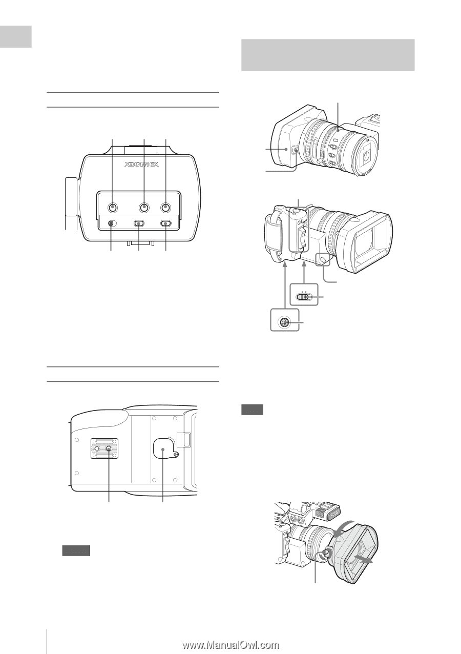
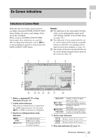
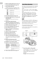
Overview 1. SHOT TRANSITION operation block (page 78) 2. TC/U-BIT/DURATION (time data selection) button (page 67, page 95) Viewfinder control panel Zoom Lens VCL-614B2X (Supplied) Lens control block (page 21) 1 23 PEAKING CONTRAST BRIGHT MIRROR IMAGE DISPLAY/BATT INFO ZEBRA OFF ON RREECVIEW RELEASE STARSTT/OP EXPAFNODCEUDS 1.9 2.8 4 5.6 1 2 AF MFFull 10 15 30 3 5 10 ft mm 5.8 10 15 25 40 81.2 SSHTOEATDY IRIS MANU AUTO MACRO OFF ON FOCUS MANPUUSHAUATFO C 16 8 Controls on the grip (page 21) 4 56 1. PEAKING control (page 62) 2. CONTRAST control (page 30) 3. BRIGHT control (page 30) 4. MIRROR IMAGE switch (page 31) 5. DISPLAY/BATT INFO button (page 23) 6. ZEBRA button (page 54) Bottom 1 2 1. Tripod receptacle Note Check that the size of the hole matches the screw of the tripod. If they do not match, the camcorder cannot be attached to the tripod securely. 2. Backup battery holder (page 144) 20 Parts Identifications ZOOM MANU SERVO 3 Cover of the lens control block (See "Note" below.) LENS REMOTE 4 1. Lens hood 2. Lens cap open/close lever (page 47) 3. ZOOM switch (page 59) 4. LENS REMOTE connector (page 61) Note The lens is properly adjusted at the factory. Do not touch the controls of the lens control block. To remove the lens hood 1 Loosen the hood fixing screw, 2 turn the hood in the direction of the arrow, 3 then pull it out. MONITOR VOL SEL/SET IL CANCEL PAUSE NEXT L EC STOP F FWD J R A TRANSSIHTIOTON CH-1 AUDIO IN CH-2 LINE MIC MIC+48V LINE MIC MIC+48V 2 STARSTT/OP EXPAFNODCEUDS RREECVIEW RELEASE LOCK RELEASE 1 3 Hood fixing screw
-
 1
1 -
2
-
3
-
4
-
5
-
6
-
7
-
8
-
9
-
10
-
11
-
12
-
13
-
14
-
 15
15 -
 16
16 -
 17
17 -
 18
18 -
 19
19 -
 20
20 -
 21
21 -
 22
22 -
 23
23 -
 24
24 -
 25
25 -
26
-
27
-
28
-
29
-
30
-
31
-
32
-
33
-
34
-
35
-
36
-
37
-
38
-
39
-
40
-
41
-
42
-
43
-
44
-
45
-
46
-
47
-
48
-
49
-
50
-
51
-
52
-
53
-
54
-
55
-
56
-
57
-
58
-
59
-
60
-
61
-
62
-
63
-
64
-
65
-
66
-
67
-
68
-
69
-
70
-
71
-
72
-
73
-
74
-
75
-
76
-
77
-
78
-
79
-
80
-
81
-
82
-
83
-
84
-
85
-
86
-
87
-
88
-
89
-
90
-
91
-
92
-
93
-
94
-
95
-
96
-
97
-
98
-
99
-
100
-
101
-
102
-
103
-
104
-
105
-
106
-
107
-
108
-
109
-
110
-
111
-
112
-
113
-
114
-
115
-
116
-
117
-
118
-
119
-
120
-
121
-
122
-
123
-
124
-
125
-
126
-
127
-
128
-
129
-
130
-
131
-
132
-
133
-
134
-
135
-
136
-
137
-
138
-
139
-
140
-
141
-
142
-
143
-
144
-
145
-
146
-
147
-
148
-
149
-
150
-
151
-
152
-
153
-
154
-
155
-
156
-
157
-
158
-
159
-
160
-
161
 |
 |