Sony RCP-1500 Operation Guide - Page 23
Panel control/status display block RCP-1500, PANEL ACTIVE button, NETWORK indicator, ALARM indicator
 |
View all Sony RCP-1500 manuals
Add to My Manuals
Save this manual to your list of manuals |
Page 23 highlights
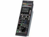
Panel control/status display block (RCP-1500) a PANEL ACTIVE button This button is for the control permission. It also serves as a function for preventing unintentional operation because a camera cannot be controlled from this control panel when this button and the PARA button are not lit. Note If the connection to the master breaks off in MCS mode system, panel active operations are not possible. In this case, a long press of the PANEL ACTIVE button forces the availability of the panel active. b NETWORK indicator This indicates the status of the network connection. Lighting state On Flashing Off Meaning Connected to a control device. A control device cannot be found. Cannot connect to the camera network. Alternatively, the mode is LEGACY. c ALARM indicator This lights red when a system error occurs and the selfdiagnosis function is operating on the camera head or CCU/ HDCU. d PREVIEW button This button is for outputting preview key signals from the EXT I/O connector. e CABLE indicator This indicates the communication state of the camera head and CCU. Lighting state On (green) On (yellow) On (red) Off Meaning The reception state is good. The reception level is low. The reception level is extremely low. The power of the camera is off. Alternatively, a communication error occurred. f CALL button This button is for communication. If it is pressed, the tally state for the camera or CCU changes, and a call signal is sent. Likewise, a call signal can be received from another device. When a call signal is sent (or received), this button lights and the call sound plays. The call sound can be selected in the menu. 23
-
 1
1 -
2
-
3
-
4
-
5
-
6
-
7
-
8
-
9
-
10
-
11
-
12
-
13
-
14
-
15
-
16
-
17
-
 18
18 -
 19
19 -
 20
20 -
 21
21 -
 22
22 -
 23
23 -
 24
24 -
 25
25 -
 26
26 -
 27
27 -
 28
28 -
29
-
30
-
31
-
32
-
33
-
34
-
35
-
36
-
37
-
38
-
39
-
40
-
41
-
42
-
43
-
44
-
45
-
46
-
47
-
48
-
49
-
50
-
51
-
52
-
53
-
54
-
55
-
56
-
57
-
58
-
59
-
60
-
61
-
62
-
63
-
64
-
65
-
66
-
67
-
68
-
69
-
70
-
71
-
72
-
73
-
74
-
75
-
76
-
77
-
78
-
79
-
80
-
81
-
82
-
83
-
84
-
85
-
86
-
87
-
88
 |
 |
