Sony STR-K790 Service Manual - Page 40
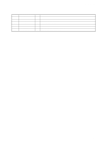
Pin No., Pin Name, Description
 |
View all Sony STR-K790 manuals
Add to My Manuals
Save this manual to your list of manuals |
Page 40 highlights
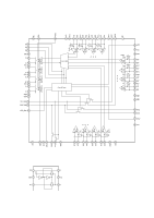
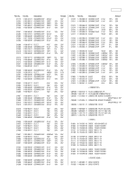
STR-K790 Pin No. Pin Name I/O Description 46 TUNER CLK O Tuner clock signal output 47 TUNER DATA O Tuner data signal output 48 STOP I AC off detect signal input 49 MD0 I Operation mode setting input 50 MD1 I Operation mode setting input 51 MD2 I Operation mode setting input 52 RDS_CLK I RDS clock signal input (AEP, UK only) 53 RDS_DATA I RDS data signal input (AEP, UK only) 54 SIRCS I Data signal input from the remote control sensor 55 HP_DETECT I Headphone signal input 56 POWER_KEY I Power switch key detect signal input 57 ADCC_INT I ADCC interrupt input 58 POWER_RY O Power relay control signal output 59 VOL IC_CL O Volume IC clock signal output 60 VOL IC_DA O Volume IC data and latch signal output 61 PROTECTOR I Protector status detect signal input 62 HP_RY O Headphone relay control signal output 63 FUSE_DETECT I Fuse detect signal input 64 VOL_ENCODER (B) I Volume signal input from rotary encoder 65 VOL_ENCODER (A) I Volume signal input from rotary encoder 66 FRONT_RY/DG51_FB O Front A speaker relay control signal output 67 FRONT_B_RY/DG51_FA O Front B speaker control signal output 68 DC-CONTROL O Center speaker relay control signal output 69 C/REAR/SB_RY O Center, rear, surround back speaker control signal output 70 SW_RY O Sub woofer control signal output 71 NC O Not used (Open) 72 BRIDGABLE_RY O Bridgeable relay control output (not used) 73 DO/SD/ST I Frequency data signal input from the tuner 74 SLATCH O Latch signal output to the tuner 75 V_SW3 O Composite video signal select 3 (not used) 76 V_SW4 O Composite video signal select 4 (not used) 77 RSTX I System reset input 78 COMP MUTE O Composite video muting signal output (not used) 79 XIA - Not used (Open) 80 XOA - Not used (ground) 81 VSS - Ground terminal 82 X0 - Connection for a crystal resonator 83 X1 - Connection for a crystal resonator 84 VCC3 - Power supply (+3.3V) 85 HDMI_S2 O HDMI select 2 (not used) 86 HDMI_S1 O HDMI select 1 (AEP, UK only) 87 HDMI_OED O HDMI output enable (AEP, UK only) 88 HDMI_PRE O HDMI PRE (AEP, UK only) 89 HDMI_CTRL O HDMI board control (AEP, UK only) 90 COMP_S2 O Composite video select 2 (not used) 91 COMP_S1 O Composite video select 1 (not used) 92 BST_SEL O BST signal output terminal 93 XMODE O Reset signal output to DIR 94 CKSEL 1 O CKSEL control signal output to DIR 40
-
 1
1 -
2
-
3
-
4
-
5
-
6
-
7
-
8
-
9
-
10
-
11
-
12
-
13
-
14
-
15
-
16
-
17
-
18
-
19
-
20
-
21
-
22
-
23
-
24
-
25
-
26
-
27
-
28
-
29
-
30
-
31
-
32
-
33
-
34
-
 35
35 -
 36
36 -
 37
37 -
 38
38 -
 39
39 -
 40
40 -
 41
41 -
 42
42 -
 43
43 -
 44
44 -
 45
45 -
46
-
47
-
48
-
49
-
50
-
51
-
52
-
53
-
54
-
55
-
56
 |
 |