Sony VPL EX7 Operating Instructions - Page 14
Connector Panel, VIDEO IN connector, INPUT A connector - vpl ex70
 |
UPC - 027242761933
View all Sony VPL EX7 manuals
Add to My Manuals
Save this manual to your list of manuals |
Page 14 highlights
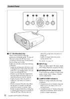
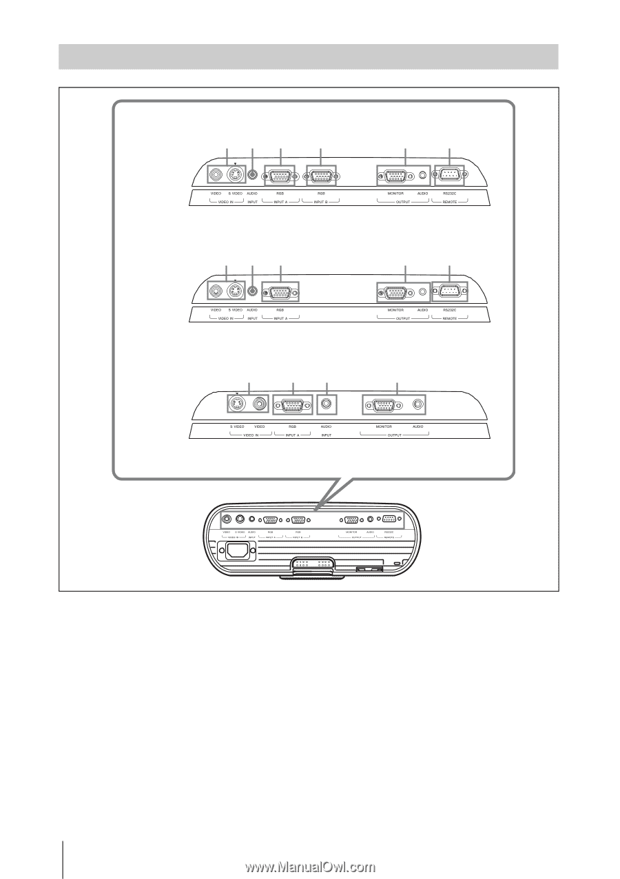
Connector Panel VPL-EX70 1 2 3 4 56 VPL-EX7 1 2 3 56 VPL-ES7 1 32 5 a VIDEO IN connector • S VIDEO (mini DIN 4-pin): Connects to the S video output of video equipment. • VIDEO (phone type): Connects to the video output of video equipment. b AUDIO INPUT connector Inputs audio signal attached to the image from INPUT A, INPUT B (VPL-EX70 only) or VIDEO. c INPUT A connector RGB (HD D-sub 15-pin, female): Inputs a computer signal, video GBR signal, component signal, or DTV signal depending on the connected equipment. Connects to the output connector of equipment using the supplied cable or an optional cable. For details, see "Connecting a Computer" on page 18 and "Connecting a VCR" on page 19. 14 Location and Function of Controls
-
 1
1 -
2
-
3
-
4
-
5
-
6
-
7
-
8
-
 9
9 -
 10
10 -
 11
11 -
 12
12 -
 13
13 -
 14
14 -
 15
15 -
 16
16 -
 17
17 -
 18
18 -
 19
19 -
20
-
21
-
22
-
23
-
24
-
25
-
26
-
27
-
28
-
29
-
30
-
31
-
32
-
33
-
34
-
35
-
36
-
37
-
38
-
39
-
40
-
41
-
42
-
43
-
44
-
45
-
46
-
47
-
48
-
49
-
50
-
51
-
52
-
53
-
54
-
55
-
56
-
57
-
58
-
59
-
60
 |
 |
14
Location and Function of Controls
a
VIDEO IN connector
•
S VIDEO (mini DIN 4-pin):
Connects to the S video output of
video equipment.
•
VIDEO (phone type):
Connects to the video output of video
equipment.
b
AUDIO INPUT connector
Inputs audio signal attached to the image
from INPUT A, INPUT B (VPL-EX70
only) or VIDEO.
c
INPUT A connector
RGB (HD D-sub 15-pin, female):
Inputs a computer signal, video GBR
signal, component signal, or DTV signal
depending on the connected equipment.
Connects to the output connector of
equipment using the supplied cable or an
optional cable.
For details, see “Connecting a
Computer” on page 18 and
“Connecting a VCR” on page 19.
Connector Panel
1
3
5
6
1
3
4
5
6
1
3
2
5
VPL-EX70
VPL-EX7
VPL-ES7
2
2