Sony XDSPD1000 User Manual (XDS-PD1000 and XDS-PD2000 Operation Manual for Fir - Page 15
Names and Functions of Parts, Front Panel
 |
View all Sony XDSPD1000 manuals
Add to My Manuals
Save this manual to your list of manuals |
Page 15 highlights
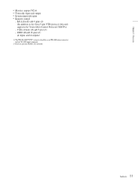
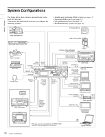
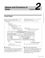
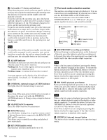
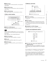
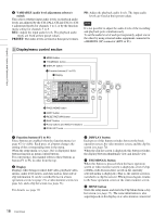
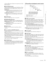
Chapter 2 Names and Functions of Parts Names and Functions of Parts 2 Chapter Front Panel The names and symbols of buttons and knobs on the front panel are color coded according to function. White: Function when the button or knob is operated independently. Orange: Function when the button is operated with the SHIFT button held down. Blue: Function related to thumbnail operations. 1 PHONES jack 2 LEVEL adjustment knob 3 On/standby (1) button and indicator 4 ALARM indicator 5 INTERNAL ACCESS indicator 6 MAINTENANCE connector 2 Disc control section (see page 17) 7 REMOTE button 1 Port and media selection section (see page 16) 3 Memory card slots (see page 17) 5 Display/menu control section (see page 18) 8 KEY INHI switch 4 Audio level adjustment section (see page 17) 7 Shuttle/jog/variable-speed playback control section (see page 20) 6 Recording and playback control section (see page 19) a PHONES jack This is a standard stereo jack. Connect stereo headphones to monitor the audio during recording and playback. (Nonaudio signals are muted.) The monitored channel is selected with MONITR L and MONITR R on the HOME page of the function menu (see page 45). b LEVEL (volume) adjustment knob Adjust the volume of headphones with this knob. You can also cause this knob to simultaneously adjust the output volume from the ANALOG AUDIO MONITOR/ OUTPUT2 R/1, L/2 connectors on the rear panel. To do this, set setup menu item 114 AUDIO MONITOR OUTPUT LEVEL to "variable". 15 Front Panel
-
 1
1 -
2
-
3
-
4
-
5
-
6
-
7
-
8
-
9
-
 10
10 -
 11
11 -
 12
12 -
 13
13 -
 14
14 -
 15
15 -
 16
16 -
 17
17 -
 18
18 -
 19
19 -
 20
20 -
21
-
22
-
23
-
24
-
25
-
26
-
27
-
28
-
29
-
30
-
31
-
32
-
33
-
34
-
35
-
36
-
37
-
38
-
39
-
40
-
41
-
42
-
43
-
44
-
45
-
46
-
47
-
48
-
49
-
50
-
51
-
52
-
53
-
54
-
55
-
56
-
57
-
58
-
59
-
60
-
61
-
62
-
63
-
64
-
65
-
66
-
67
-
68
-
69
-
70
-
71
-
72
-
73
-
74
-
75
-
76
-
77
-
78
-
79
-
80
-
81
-
82
-
83
-
84
-
85
-
86
-
87
-
88
-
89
-
90
-
91
-
92
-
93
-
94
-
95
-
96
-
97
-
98
-
99
-
100
-
101
-
102
-
103
-
104
-
105
-
106
-
107
-
108
-
109
-
110
-
111
-
112
-
113
-
114
-
115
-
116
-
117
-
118
-
119
-
120
-
121
-
122
-
123
-
124
-
125
-
126
-
127
-
128
-
129
-
130
-
131
-
132
-
133
-
134
-
135
-
136
-
137
-
138
-
139
-
140
-
141
-
142
-
143
-
144
-
145
-
146
-
147
-
148
-
149
-
150
-
151
-
152
-
153
-
154
-
155
-
156
-
157
-
158
-
159
-
160
-
161
 |
 |