Sony XDSPD1000 User Manual (XDS-PD1000 and XDS-PD2000 Operation Manual for Fir - Page 158
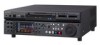
REMOTE 9P R/P2, P1 connectors, MEMORY ACCESS A/B lamps
 |
View all Sony XDSPD1000 manuals
Add to My Manuals
Save this manual to your list of manuals |
Page 158 highlights
H HD/SD-SDI INPUT connector 28 HD/SD-SDI signal input/output section 27 HDMI OUTPUT connector 26 HD-SDI MONITOR/OUTPUT2 1, 2 connector 28 HD-SDI OUTPUT1 1, 2 (SUPER) connectors 28 HOME button 19 I IN/OUT indicators 19 Initial setup 31 INTERNAL ACCESS indicator 16 INTERNAL button 16 J JOG indicator 20 Jog mode 62 Jog/shuttle direction indicators 20 K KEY INHI switch 16 L LEVEL adjustment knob 15 Linear editing 56 Loading/unloading disc 49 M Main power switch 29 Maintenance periodic 131 MAINTENANCE connector 16, 27 Maintenance menu 122 communication speed 127 items 122 network settings 127 operations 126 Media status display 22 MEMORY ACCESS A/B lamps 17 status indications 51 MEMORY button 17 Memory card slots 17 Menu bank setting 103 changing settings 104 Clip F Menu 76 Clip Menu 75 configuration 99 function menu 45 maintenance menu 122 returning to default settings 105 setup menu 99 MENU button 18 Metadata 145 MONITOR connector 27 N Names and functions of parts 15 Network assigning IP address automatically 127 connector 27 setting IP address 127 settings 127 NEXT button 19 Normal speed playback 61 O On/standby button (1) and indicator 16 Operating hours meter 131 display modes 131 displaying 131 exiting 131 Operation status display 23 P PAGE button 19 PB1 PORT button 16 PCIe expansion slot 26 PHONES jack 15 PLAY button 19 Playback 59 chase play 63 EDL 81 jog mode 62 normal speed 61 pulldown playback 60 settings 59 shuttle mode 62 using thumbnails 63 variable-speed mode 63 Playback condition display 44 mark 43 Port and media selection section 16 Power supply section 29 Preparation Initial setup 31 PREV button 19 Professional Disc 48 Proxy AV data 10 PUSH SET knob 19 R Rear panel 26 REC button 19 REC INHI indicator 20 REC/PB2 PORT button 16 Recording 53 level adjustment 55 mixed recording 55 settings 53 Recording and playback control section 19 Recording/playback format 23 Redundant power supply unit installation section 27 REF. VIDEO INPUT connectors 27 Reference signal 22 REMOTE (9P) R/P2, P1 connectors 27 REMOTE button 16 RESET/RETURN button 19 Returning to factory default settings 105 S Salvage 69 SD-SDI MONITOR/OUTPUT2 1, 2 connector 28 SD-SDI OUTPUT1 1, 2 (SUPER) connectors 28 Setup menu basic menu 100 extended menu 106 SHIFT button 19 SHTL/JOG button 20 Shuttle mode 62 Shuttle/jog dial 20 Shuttle/jog/variable-speed playback control section 20 Slot selection lamps 17 Specifications 140 STANDBY indicator 20 Status display area 24 STOP button 19 Sub clip 80 Superimposed text information 42 Supplying power 31 SxS memory card 50 inserting 51 removing 51 switching 52 write protect switch 51 Synchronization reference signals 39 System frequency, setting 31, 40 System information 22 SYSTEM TC INPUT connector 27 T Text information 42 Index 158 Index
-
 1
1 -
2
-
3
-
4
-
5
-
6
-
7
-
8
-
9
-
10
-
11
-
12
-
13
-
14
-
15
-
16
-
17
-
18
-
19
-
20
-
21
-
22
-
23
-
24
-
25
-
26
-
27
-
28
-
29
-
30
-
31
-
32
-
33
-
34
-
35
-
36
-
37
-
38
-
39
-
40
-
41
-
42
-
43
-
44
-
45
-
46
-
47
-
48
-
49
-
50
-
51
-
52
-
53
-
54
-
55
-
56
-
57
-
58
-
59
-
60
-
61
-
62
-
63
-
64
-
65
-
66
-
67
-
68
-
69
-
70
-
71
-
72
-
73
-
74
-
75
-
76
-
77
-
78
-
79
-
80
-
81
-
82
-
83
-
84
-
85
-
86
-
87
-
88
-
89
-
90
-
91
-
92
-
93
-
94
-
95
-
96
-
97
-
98
-
99
-
100
-
101
-
102
-
103
-
104
-
105
-
106
-
107
-
108
-
109
-
110
-
111
-
112
-
113
-
114
-
115
-
116
-
117
-
118
-
119
-
120
-
121
-
122
-
123
-
124
-
125
-
126
-
127
-
128
-
129
-
130
-
131
-
132
-
133
-
134
-
135
-
136
-
137
-
138
-
139
-
140
-
141
-
142
-
143
-
144
-
145
-
146
-
147
-
148
-
149
-
150
-
151
-
152
-
 153
153 -
 154
154 -
 155
155 -
 156
156 -
 157
157 -
 158
158 -
 159
159 -
 160
160 -
 161
161
 |
 |