Stihl FS 120 Product Instruction Manual - Page 26
Fitting the Carrying Eye, Mounting the Deflector
 |
View all Stihl FS 120 manuals
Add to My Manuals
Save this manual to your list of manuals |
Page 26 highlights
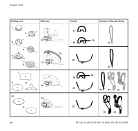
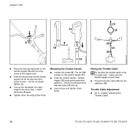
Fitting the Carrying Eye English / USA Mounting the Deflector 249BA017 KN 002BA142 KN 002BA102 KN STOP 2 1 : Press down the trigger interlock (1) and squeeze the throttle trigger (2) (full throttle) - this sets the throttle cable correctly. 1 1 2 1 3 2 3 : For position of carrying eye1) see "Parts and Controls" : Place the clamp (1) with the tapped hole on the left-hand side of the drive tube. : Squeeze the two ends of the clamp together and hold in that position. : Insert M 6 x 14 screw (2). : Line up the carrying eye. : Tighten down the screw firmly. Mounting the deflector 1 = Deflector approved for all cutting tools 2 = Deflector approved for use with mowing heads only : Place the deflector on the gearhead. : Fit the plate (3) and line it up. : Insert M 5 x 18 screws and tighten down firmly. 1) Included as standard or available as special accessory FS 120, FS 120 R, FS 200, FS 200 R, FS 250, FS 250 R 25
-
 1
1 -
2
-
3
-
4
-
5
-
6
-
7
-
8
-
9
-
10
-
11
-
12
-
13
-
14
-
15
-
16
-
17
-
18
-
19
-
20
-
 21
21 -
 22
22 -
 23
23 -
 24
24 -
 25
25 -
 26
26 -
 27
27 -
 28
28 -
 29
29 -
 30
30 -
 31
31 -
32
-
33
-
34
-
35
-
36
-
37
-
38
-
39
-
40
-
41
-
42
-
43
-
44
-
45
-
46
-
47
-
48
-
49
-
50
-
51
-
52
-
53
-
54
-
55
-
56
-
57
-
58
-
59
-
60
-
61
-
62
-
63
-
64
-
65
-
66
-
67
-
68
-
69
-
70
-
71
-
72
-
73
-
74
-
75
-
76
-
77
-
78
-
79
-
80
-
81
-
82
-
83
-
84
-
85
-
86
-
87
-
88
-
89
-
90
-
91
-
92
-
93
-
94
-
95
-
96
-
97
-
98
-
99
-
100
-
101
-
102
-
103
-
104
-
105
-
106
-
107
-
108
-
109
-
110
-
111
-
112
-
113
-
114
 |
 |
