Sub-Zero BI-36R Built-In Installation Guide - Page 27
Models Bi-42sd And Bi-48sd, Grille Panel Assembly
 |
View all Sub-Zero BI-36R manuals
Add to My Manuals
Save this manual to your list of manuals |
Page 27 highlights
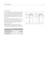
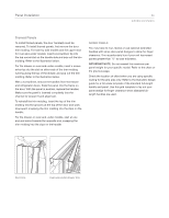
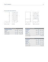
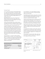
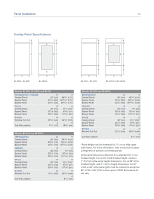
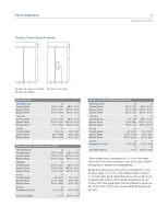
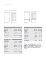
Panel Installation 27 subzero.com/specs Overlay Panels MODELS BI-42SD AND BI-48SD The dispenser area of models BI-42SD and BI-48SD has been engineered to enable the use of the overlay or flush inset panel application. Installing overlay or flush inset panels for these models is the same procedure as for other built-in models. The refrigerator door panel will need to accommodate a cut-out for the glasswell bezel. To remove the glasswell bezel for an overlay or flush inset model BI-42SD or BI-48SD, the water grille and touch pad must be removed. Lift the water grille up and out. Next, remove the touch pad assembly by removing the center plastic mandrel supports. Carefully tilt the touch pad out and disconnect the wire harness (blue side up) from the back side of the touch pad. Remove the bezel by removing the four screws. Insert the overlay or flush inset panel into the door trim. Reverse the procedure to install the bezel, touch pad and water grille. To install the plastic rivets, insert rivets through the touch pad and into the control housing and secure by pressing mandrels into the body of the rivets. Refer to the illustrations below. IMPORTANT NOTE: The total panel thickness (including backer and spacer, if used) in the glasswell bezel area can range from 1/4" (6) to a maximum of 11/8" (29). If the panel is thicker, provisions must be made to rout out a space to accommodate the bezel surrounding the glasswell. GRILLE PANEL ASSEMBLY Remove the grille panel assembly as described on page 16. Remove the top two corner screws and pull away the top frame. Slide the panel into position in the grille frame. If you are using a grille panel 1/4" (6) or thinner, you will need to install a filler. Reattach the top frame by reinstalling the two top corner screws. Install the grille panel assembly onto the unit, by reversing the grille removal procedure outlined on page 16. Refer to specifications for overlay grille panels on pages 28-29 and the illustrations on the previous page for the exact sizing of all three panels. Do not exceed the panel dimensions listed for the appropriate overlay grille panel you are specifying. The overlay decorative panel cannot be any larger or it may restrict the air flow to the compressor area and cause problems with the operation of the Sub-Zero unit. LOCK INDICATOR ICE WATER LIGHT WATER GRILLE BEZEL Dispenser glasswell bezel. Glasswell bezel removal.
-
 1
1 -
2
-
3
-
4
-
5
-
6
-
7
-
8
-
9
-
10
-
11
-
12
-
13
-
14
-
15
-
16
-
17
-
18
-
19
-
20
-
21
-
 22
22 -
 23
23 -
 24
24 -
 25
25 -
 26
26 -
 27
27 -
 28
28 -
 29
29 -
 30
30 -
 31
31 -
 32
32 -
33
-
34
-
35
-
36
-
37
-
38
-
39
-
40
 |
 |
