TASCAM CD-RW901 Owners Manual - Page 12
Display
 |
View all TASCAM CD-RW901 manuals
Add to My Manuals
Save this manual to your list of manuals |
Page 12 highlights
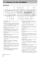
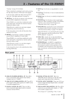
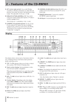
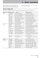
2 − Features of the CD-RW901 b ATT control right and left Use a small Phillips screwdriver with these attenuators to reduce the output level from either the right or left balanced analog output. The adjustable level is up to -10 dB. n ANALOG OUT (BALANCED) (L, R) These XLR connectors output analog audio signals at +4 dBu to suitably-equipped units. The wirings are: 1=grounding, 2=hot, 3=cold. m CONTROL I/O (parallel) terminal Use this 15-pin D-sub connector to connect the unit to suitablyequipped units, allowing control of the CD-RW901. The pinouts of this connector are described (see Connections" on page 9). , CONTROL I/O (RS-232C) terminal RS-232C compatible serial control from an external PC can be performed. . REMOTE IN terminal Connects the supplied RC-RW901 remote control unit. / AC IN jack Connects the power cable supplied. Display !@# $ % ^ & * () Q W E R SD F G T Y U I O P A HJ This display shows various types of operation information, including CD disc information, deck operation modes, and menu status. ! TOC The TOC indicator lights up red when a loaded disc contains TOC (Table of Contents) data. @ Track number display During playback or selection, the track number is displayed. When Incremental playback is on, and when in playback or playback ready mode, the TRACK indicator blinks. # MP3 The MP3 indicator lights when a MP3 disc is in the deck. $ Counter display Depending on the time display mode, TOTAL or REMAIN are lit. The counter display indication are in minutes (three digits) and seconds (two digits). % KEY The KEY indicator lights when Key Control is on. ^ PITCH The PITCH indicator lights when Pitch Control is on. & A.CUE The A.CUE indicator lights when Auto Cue is on. * A.READY The A.READY indicator lights when Auto Ready is on. ( A. TRACK The A.TRACK indicator lights when the Auto Track is on. ) Meter This displays the playback level, as well as the input level of the source device. Q A-B The A-B indicator lights when the A-B repeat function is on. Also, this flashes until a "B-point" is entered. W REPEAT The REPEAT indicator lights when the Repeat function is on. E SYNC The SYNC indicator lights up when SYNC is on. R REC When the SRC function is on, this lights during recording, or in recording standby mode. When the SRC function is off, this flashes during recording, or in recording standby mode. 12 TASCAM CD-RW901
-
 1
1 -
2
-
3
-
4
-
5
-
6
-
 7
7 -
 8
8 -
 9
9 -
 10
10 -
 11
11 -
 12
12 -
 13
13 -
 14
14 -
 15
15 -
 16
16 -
 17
17 -
18
-
19
-
20
-
21
-
22
-
23
-
24
-
25
-
26
-
27
-
28
-
29
-
30
-
31
-
32
-
33
-
34
-
35
-
36
-
37
-
38
-
39
-
40
 |
 |
