TP-Link TD-8811 User Guide - Page 8
Hardware Installation Guide, 2.1 System requirement, 2.2 LED explanation - adsl
 |
UPC - 845973030261
View all TP-Link TD-8811 manuals
Add to My Manuals
Save this manual to your list of manuals |
Page 8 highlights
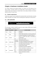
TD-8811 External ADSL2+ ROUTER Chapter 2. Hardware Installation Guide The TD-8811 maintains three separate interfaces, one Ethernet, one USB interface and one ADSL interface. The Router should not be located where it will be exposed to moisture or excessive heat. Place the Router in a location where it can be safely connected to the various devices as well as to a power source. 2.1 System requirement Confirm your computer has been installed with networking interface card (NIC) before connecting ADSL2+ ROUTER to your computer, with the operating system supporting the TCP/IP protocol. 2.2 LED explanation The front panel of ADSL2+ ROUTER includes one power indicator (RED) and five function indicators (GREEN), as explained in chart 1-1: Indicator Description Power Power Act Data Alarm Mistake ADSL ADSL status LAN Ethernet USB USB status Status On Off On Off On Off Slow flash Quick flash On Off On Off Flash On Off Flash Function Details Power OK Power fail There is data transmitting or receiving on WAN port No data is transmitting or receiving on WAN port There is a mistake when ADSL is transmitting or receiving data ADSL works normally Self-detecting when power on The LINE is connecting to the ISP's network The LINE has connected to ISP's network The LINE port has no connection LAN port works normally Connection on LAN port is abnormal Data is transmitting or receiving on LAN port Connection to telecom network is OK Connection on USB port is abnormal Data is transmitting or receiving Chart 1-1 4
-
 1
1 -
2
-
 3
3 -
 4
4 -
 5
5 -
 6
6 -
 7
7 -
 8
8 -
 9
9 -
 10
10 -
 11
11 -
 12
12 -
 13
13 -
14
-
15
-
16
-
17
-
18
-
19
-
20
-
21
-
22
-
23
-
24
-
25
-
26
-
27
-
28
-
29
-
30
-
31
-
32
-
33
-
34
-
35
-
36
-
37
-
38
-
39
 |
 |
