TP-Link TD-8840T User Guide - Page 9
Hardware Installation - lan ports
 |
UPC - 845973060176
View all TP-Link TD-8840T manuals
Add to My Manuals
Save this manual to your list of manuals |
Page 9 highlights
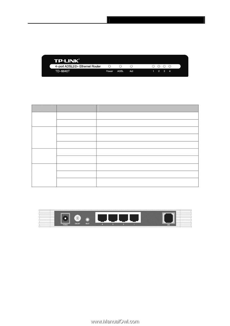
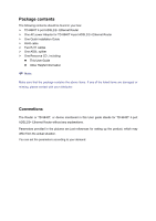
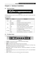
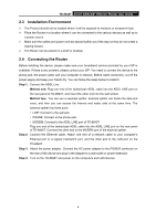
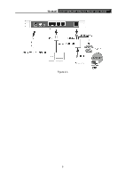
TD-8840T 4-port ADSL2/2+ Ethernet Router User Guide Chapter 2. Hardware Installation 2.1 The Front Panel Figure 2-1 The Router's LEDs are located on the front panel (View from left to right). For details, please refer to LED Explanation. LED Explanation: Name Status On Power Off Slow flash ADSL Quick flash On Flash Act Off On 1~4 (LAN) Off Flash Indication Power OK Power fail Connection to telecom network is abnormal Connecting to the telecom network Connection to telecom network is OK There is data transmitting or receiving on WAN port No data transmitting or receiving on WAN port 1~4 (LAN) port normal Connection on 1~4 (LAN) port abnormal Data transmitting or receiving on 1~4 (LAN) port 2.2 The Back Panel The following parts are located on the rear panel (View from left to right). Figure 2-2 ¾ POWER: The Power plug is where you will connect the power adapter. ¾ On/OFF: The switch for the power. ¾ RESET: There are two ways to reset the Router's factory defaults. Method one: When the device is working, please press the reset button of the Router, keep the reset button pressed down for more than five seconds. Method two:Restore the default setting from "Maintenance-SysRestart" of the Router's Web-based Utility. ¾ LAN (1~4): Through the port, you can connect the Router to your PC or the other Ethernet network devices. ¾ LINE: Through the port, you can connect the Router with the telephone. 3
-
 1
1 -
2
-
3
-
 4
4 -
 5
5 -
 6
6 -
 7
7 -
 8
8 -
 9
9 -
 10
10 -
 11
11 -
 12
12 -
 13
13 -
 14
14 -
15
-
16
-
17
-
18
-
19
-
20
-
21
-
22
-
23
-
24
-
25
-
26
-
27
-
28
-
29
-
30
-
31
-
32
-
33
-
34
-
35
-
36
-
37
-
38
-
39
-
40
-
41
-
42
-
43
-
44
-
45
-
46
-
47
-
48
-
49
-
50
-
51
-
52
-
53
-
54
-
55
-
56
 |
 |