TP-Link TD-W9970B TD-W9970BEU V1 User Guide - Page 16
Connecting the Modem Router, Step 1, Method one
 |
View all TP-Link TD-W9970B manuals
Add to My Manuals
Save this manual to your list of manuals |
Page 16 highlights
TD-W9970/TD-W9970B 300Mbps Wireless N USB VDSL/ADSL Modem Router User Guide Note: The diameter of the screw, 3.5mm
-
 1
1 -
2
-
3
-
4
-
5
-
6
-
7
-
8
-
9
-
10
-
 11
11 -
 12
12 -
 13
13 -
 14
14 -
 15
15 -
 16
16 -
 17
17 -
 18
18 -
 19
19 -
 20
20 -
 21
21 -
22
-
23
-
24
-
25
-
26
-
27
-
28
-
29
-
30
-
31
-
32
-
33
-
34
-
35
-
36
-
37
-
38
-
39
-
40
-
41
-
42
-
43
-
44
-
45
-
46
-
47
-
48
-
49
-
50
-
51
-
52
-
53
-
54
-
55
-
56
-
57
-
58
-
59
-
60
-
61
-
62
-
63
-
64
-
65
-
66
-
67
-
68
-
69
-
70
-
71
-
72
-
73
-
74
-
75
-
76
-
77
-
78
-
79
-
80
-
81
-
82
-
83
-
84
-
85
-
86
-
87
-
88
-
89
-
90
-
91
-
92
-
93
-
94
-
95
-
96
-
97
-
98
-
99
-
100
-
101
-
102
-
103
-
104
-
105
-
106
-
107
-
108
-
109
-
110
-
111
-
112
-
113
-
114
-
115
-
116
-
117
-
118
-
119
-
120
-
121
 |
 |

TD-W9970/TD-W9970B
300Mbps Wireless N USB VDSL/ADSL Modem Router User Guide
8
Note:
The diameter of the screw, 3.5mm<D<7.8mm, and the distance of two screws is 107.5mm. The
screw that project from the wall need around 4mm based, and the length of the screw need to be
at least 20mm to withstand the weight of the product.
2.3 Connecting the Modem Router
Before installing the device, please make sure your broadband service provided by your ISP is
available. If there is any problem, please contact your ISP. Before cable connection, cut off the
power supply and keep your hands dry. You can follow the steps below to install it.
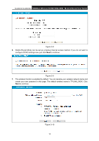
Step 1:
Connect the DSL Line.
Method one:
Plug one end of the twisted-pair DSL cable into the VDSL port on the rear
panel of the modem router, and insert the other end into the wall socket.
Method two
:
You can use a separate splitter. External splitter can divide the data and
voice, and then you can access the Internet and make calls at the same time. The
external splitter has three ports:
• LINE: Connect to the wall jack
• PHONE: Connect to t
he phone sets
• MODEM: Connect to the
VDSL port of the modem router
Plug one end of the twisted-pair DSL cable into the VDSL port on the rear panel of the
modem router. Connect the other end to the MODEM port of the external splitter.
Step 2:
Connect the Ethernet cable. Attach one end of a network cable to your computer’s
Ethernet port or a regular hub/switch port, and the other end to the LAN port on the
modem router.
Step 3:
Power on the computers and LAN devices.
Step 4:
Attach the power adapter. Connect the power adapter to the power connector on the rear
of the device and plug in the adapter to an electrical outlet or power extension. The
electrical outlet shall be installed near the device and shall be easily accessible.
Figure 2-2