TP-Link TL-SC3171G User Guide
TP-Link TL-SC3171G Manual
 |
UPC - 845973054038
View all TP-Link TL-SC3171G manuals
Add to My Manuals
Save this manual to your list of manuals |
TP-Link TL-SC3171G manual content summary:
- TP-Link TL-SC3171G | User Guide - Page 1
IP Surveillance System User's manual - TP-Link TL-SC3171G | User Guide - Page 2
System Requirement 1 1.2 Installation ...1 1.3 Quick Start...5 2.1 Start ...11 2.2 Information Window 13 2.3 PTZ Camera Control 13 2.3.1. Preset/ Talk:...14 2.4.2. Connect/ Disconnect 14 2.4.3. Show Camera: ...15 2.4.4. Snapshot:...15 2.4.5. Manual Record 15 2.4.6. Toggle Full Screen 15 3.1 - TP-Link TL-SC3171G | User Guide - Page 3
Schedule Manually 25 4.4 Copy Schedule ...26 4.5 Week Mode ...26 4.5.1. Default: Camera ...37 6.2.1. Add Camera...37 6.2.2. Camera Parameter 39 6.2.3. OSD Setting:...39 6.2.4. IP Camera / Video Server Setting Panel 40 6.3 Setting - I/O Device 40 6.4 Setting - PTZ Config 41 6.5 Setting - User - TP-Link TL-SC3171G | User Guide - Page 4
6.9.1. Backup...46 6.9.2. Delete Recorded Information from the System 48 6.10 Network Service ...50 6.10.1. Live Streaming Server 50 6.11 About Main Console 53 7.1 Setup Panel...55 7.1.1. Setup Panel-Server 56 7.2 Show Camera(s) On the Display Screen 56 7.2.1. Log In/ Log Out 57 7.2.2. Server - TP-Link TL-SC3171G | User Guide - Page 5
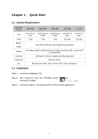
Total FPS at CIF CPU RAM Motherboard Display Ethernet Hard Disk OS 480~640 360~480 240~360 120~240 0~120 Intel Core Vista / Windows 7 1.2 Installation Step 1: Insert the Installation CD. Step 2: Run Setup.exe from the CD-ROM driver/ directory to install. Step 3: Check the option - TP-Link TL-SC3171G | User Guide - Page 6
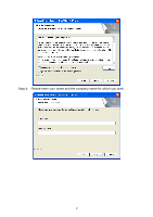
Step 4: Please enter your name and the company name for which you work. 2 - TP-Link TL-SC3171G | User Guide - Page 7
all program features into the default directory. Check the option "Complete". All program features will be installed. [Require the most disk space.] Press the "install" to start the installation. Custom Setup Type: Install the system to a preferred directory. Or select whichever feature(s) you - TP-Link TL-SC3171G | User Guide - Page 8
Select folder where setup will install files. Select the features setup will install. Hint: For example, select only Playback and LiveView for installation. Install and use only these features on multiple remote sites at home or anywhere with a PC. Press "Finish" to finish the installation. 4 - TP-Link TL-SC3171G | User Guide - Page 9
enjoy our Intelligent Surveillance Solution. 1.3 Quick Start Install IP camera(s) Step 1: Setup the IP camera(s) following by the instruction manual provided by the manufacturer. Step 2: Check the network between the IP camera(s) and the system. Step 3: Add the IP camera(s) to the system following - TP-Link TL-SC3171G | User Guide - Page 10
just support the IP cameras with UPnP supported. Step 5 Step 8 Step 6: Select one of the IP cameras that are available; check the option and enter the username and password. Step 7: Click OK to add the camera. Step 8: Click "Insert" to insert the IP cameras. Step 9: Enter the IP address or - TP-Link TL-SC3171G | User Guide - Page 11
Set Schedule Step 1: Go to Start > All programs > IP Surveillance > Main Console. Step 3 Step 2: Type in user name and password and log on to the system. Step 3: In the Main Console, go to Schedule. Step 4: By default, when inserting a camera to the system, the recording schedule is automatically - TP-Link TL-SC3171G | User Guide - Page 12
Recording Schedule" and "Start Smart Guard System" to initiate the two functions. Step 4 Playback Step 1: Go to Start > All programs > IP Surveillance > Main Console. Step 2: Type in user name and password and log on to the system. Step 3: In the Main Console, go to Playback. Step 3 Step 4: In - TP-Link TL-SC3171G | User Guide - Page 13
bars to select playback section. Click OK to return to Playback Console. Step 6: The recorded files are ready to view now. 9 - TP-Link TL-SC3171G | User Guide - Page 14
2. Main Console This is the main operation system - to activate, schedule recording, setup smart guard and configure system setting. Minimize Exit EXIT: Shut down the Surveillance System or log out current user. MINIMIZE: Minimize the Main Console window. SCREEN DIVISION: Allocate the sub-screen - TP-Link TL-SC3171G | User Guide - Page 15
Divide into 1 screen(s) Divide into 10 screen(s) Divide into 13 screen(s) 2.1 Start Divide into 4 screen(s) Divide into 13 screen(s) Divide into 17 screen(s) Divide into 6 screen(s) Divide into 16 screen(s) Switch to Full screen Divide into 9 screen(s) Divide into N screen(s) Rotate all screens - TP-Link TL-SC3171G | User Guide - Page 16
See Playback on page 20 for detail. SCHEDULE: Organize recording time schedule and setup recorder configuration. See Schedule on page 30 for detail. GUARD: Add/edit type(s) , access log viewer and backup files, or setup network services. See Config on page 42 for detail. Information Window PTZ - TP-Link TL-SC3171G | User Guide - Page 17
> General Setting > General 2.3 PTZ Camera Control: Control the movement of PTZ cameras. With cameras that support PTZ control, you can move, zoom obtain the Patrol Setup dialog. From the left window, select the cameras that you would like to have in the patrol group. Align the cameras in order in - TP-Link TL-SC3171G | User Guide - Page 18
screen and get the On Screen Menu, from which you can enable move, enable digital PTZ, and connect/ disconnect the camera. 2.4.1. Enable Talk: With cameras that support two-way audio, you may select enable talk to utilize the function. 2.4.2. Connect/ Disconnect: Right click on the display screen - TP-Link TL-SC3171G | User Guide - Page 19
Camera: Select the camera to be displayed from the Show Camera Menu. 2.4.4. Snapshot: Select the snapshot function to capture a specific video image immediately. You have the options to copy the image to the clipboard or to save it. 2.4.5. Manual Record: Start recording video by selecting manual - TP-Link TL-SC3171G | User Guide - Page 20
the Playback console. EXIT: Shut down the Playback console. SCROLL BAR: Indicate the status of the playing video; drag it to where you want to review. 16 - TP-Link TL-SC3171G | User Guide - Page 21
CONTROL: Play, pause and stop the video. CUE: When playing video, click on the Cue In/ Cue Out icon at where you want to set as the starting/ ending point of a saved video clip. The Cue In and Cue Out time will be displayed on the Playback Information Window once they are set. SPEED: Control the - TP-Link TL-SC3171G | User Guide - Page 22
display by clicking on the desired layout icon. To switch to single camera display, double click on a particular sub-screen. Double click on to access the Date-Time Panel and withdraw the video record that you want to review. Withdraw the records: STEP 2 STEP 3 STEP 5 STEP4 2 Step 1: From the - TP-Link TL-SC3171G | User Guide - Page 23
the record in grey scale mode so the image displays in black and white. 3.7 Save Video Step 1: Click on the display screen to choose the camera display that you want to save as a video clip. Step 2: Set up the cue in and cue out points; the cue in and cue out - TP-Link TL-SC3171G | User Guide - Page 24
3.8 Save Image Step 1: Click on the display screen to choose the camera display from which you want to save pictures. Step 2: Click Save Image button when the image you want is shown on the screen. You may - TP-Link TL-SC3171G | User Guide - Page 25
" to select data and press "Backup". Step 2: You can adjust the Start Time and End Time you want to backup. Step 3: You can adjust the Cameras you want to backup. Step 4: You can calculate the size of the backup data. Step 5: Select the directory you want to save the backup data - TP-Link TL-SC3171G | User Guide - Page 26
the drop-down menu to view all types of events. Step 2: Choose the camera channel you wish to view or select "All" for all the channels available. the record, which is the default setting of the system. 2. A link will appear right next to each event time. By clicking on the link, the video will jump - TP-Link TL-SC3171G | User Guide - Page 27
2 Step 4 1. Main Console Startup 2. Main Console Shutdown 3. User Login 4. User Login Failed 5. Start Schedule 6. Stop Schedule 7. Execute Recycle 8. 20. Stop Remote Playback Server 21. Modify Remote Playback Server 22. IP Camera Connection Lost Step1: Choose the type of event you wish the check - TP-Link TL-SC3171G | User Guide - Page 28
day according to your setting. To setup the time schedule for each camera, you may 1. Load the preset modes or 2. Insert a new schedule manually 4.2 Load Preset Modes Click on the quality, and Normal resolution. High Security Mode: Video recording 24 hours a day with the setting of 30 FPS, the 24 - TP-Link TL-SC3171G | User Guide - Page 29
, Low quality, and Low resolution. You can adjust the sensitivity, interval and area of motion detection in the Schedule Configuration. 4.3 Insert a New Schedule Manually Step 1: Left-click and draw the bar you want to the time table. The scheduled time will show as a grey bar. Step 1 Step 2 Step - TP-Link TL-SC3171G | User Guide - Page 30
each channel/camera by repeating the process above, or simply apply the setting of a single camera to all the others. Copy to 4.5 Week Mode Schedule the cameras for each day of the week differently. In addition, you may assign extra holidays under the Week Mode. Week Mode Default Holiday Custom - TP-Link TL-SC3171G | User Guide - Page 31
4.5.1. Default: Follow the same process to setup the schedule for every day in a week. 4.5.2. Holiday: according to a special schedule(s) different from the others. 4.6 Adjust the Scheduled Setting You can manually change the setting at any time after you insert or load a period of schedule. Option - TP-Link TL-SC3171G | User Guide - Page 32
. Left-click and drag the mouse to draw a detection zone. You may define more than one zone on the screen by repeating the same process. User can also click on "All" button to select the entire detection zone. You may adjust the sensitivity and the frame interval. 4.7.3. Pre-record/ Post-record - TP-Link TL-SC3171G | User Guide - Page 33
an action with which the system will take when the specified event is detected. 5.1 Event Insert Event Step 1 There are three sources of events: Camera (video image), Digital Input (device connected to you PC) and System (condition of your hardware). You can assign multiple events by following the - TP-Link TL-SC3171G | User Guide - Page 34
Event Type. See the following instructions. 5.1.2. Event - Signal Lost Basic Enable Event: Check the box to activate. Life Cycle Automatically cancel event when event disappears: the alarm/action will be off once the abnormality is fixed or ends. Manually cancel event or event continues triggered - TP-Link TL-SC3171G | User Guide - Page 35
/action will be off once the abnormality is fixed or ends. Manually cancel event or event continues triggered: The alarm/action will continue canceled from the Main Console (Start>Open Event Report>Cancel All Events). The user currently not at the seat watching the screen will be notified by the - TP-Link TL-SC3171G | User Guide - Page 36
. Left-click and drag the mouse to draw a detection zone. You may define more than one zone on the screen by repeating the same process. User can also click on "All" button to select the entire detection zone. Start Simulation: Click the Start Simulation button and test the function on the - TP-Link TL-SC3171G | User Guide - Page 37
5.2 Action Insert Action: To setup actions responding to an unusual event. Step 1 Step 2 Step 1: Choose an event and click the "Insert Action" icon. Step 2: There are 6 types of actions: On - TP-Link TL-SC3171G | User Guide - Page 38
Chapter 6. Configuration Config Modify the setting, log viewer, backup, and network services. Click on the Config icon, select from the drop-down menu and open the Configuration panel. 34 - TP-Link TL-SC3171G | User Guide - Page 39
6.1 Setting - General Startup Panel Resolution Automatically Popup Event Report 6.1.1. Startup Check the box and activate the functions as the system starts. You may start/stop the function in Monitor panel on the Main Console. Panel Resolution Set up the resolution of the control panel. You may - TP-Link TL-SC3171G | User Guide - Page 40
the system log data that is older than the number of days set. Status Display Audio Preview Audio Preview Default Channel: Select the audio channel that you wish to hear from in "Default Channel. Preview Active Channel: Check the "Preview Active Channel" option to hear the audio from selected video - TP-Link TL-SC3171G | User Guide - Page 41
Check the boxes of the information that you wish to see in the information display window in the Main Console. Status Display 6.2 Setting - Camera 6.2.1. Add Camera Four function buttons will be included in the Setting/Camera panel if you have our Hybrid Surveillance System license for IP camera. 37 - TP-Link TL-SC3171G | User Guide - Page 42
by clicking on the Stop Scan button. Fill in the user name and password for each IP camera found and click OK to add it to the camera list. Insert: Click on the Insert icon to obtain the IP/Video Server Setting panel and add IP cameras to the list. See page 9 for details. Delete: Click on - TP-Link TL-SC3171G | User Guide - Page 43
to the system will show on the panel, click the name of the camera to adjust the setting. Camera Name: Name the camera for your convenience. Camera Settings: Set the camera parameter offered by camera vendor. Video Parameter: Adjusts the video's brightness, contrast, saturation, and color hue values - TP-Link TL-SC3171G | User Guide - Page 44
Device Description Network: Fill up the Network field (including Name, IP Address, Http Port, User Name, Password and Protocol) referring to the instruction provided by the camera manufacturer. Check "Use DNS" to use domain name instead of IP address. Device: Choose the IP camera manufacturer from - TP-Link TL-SC3171G | User Guide - Page 45
Select the device type from the drop-down menu. N/O: Normal Open. N/C: Normal Close. 6.4 Setting - PTZ Config Basic Setting Advanced Setting Install PTZ cameras following the instruction of the camera manufacturers. A PTZ camera is usually connected to the PC with RS-485/RS-422. Check the box on the - TP-Link TL-SC3171G | User Guide - Page 46
according to your PTZ camera. Advanced Setting: You may setup the pan speed, tilt speed, zoom speed and auto pan speed. Adjust the settings by dragging the bars. 6.5 Setting - User Account User Account: The administrator may manage the user accounts here. From the list on the right, highlight each - TP-Link TL-SC3171G | User Guide - Page 47
Activate auto scan to rotate the channels/ cameras on the display screen. For instance, you Load Configuration The Save/ Load Configuration function allows system users to save any specific setting as a cfg (config) -start Main Console manually. Note: MainConsole will be automatically shutdown - TP-Link TL-SC3171G | User Guide - Page 48
: Choose the type of event you want to check or select "All" from the drop-down menu for all types of events. Step 2: Select the camera you want to check the event(s) from or select "All" for all available channels. Step 3: You may view events happened on a particular date or during - TP-Link TL-SC3171G | User Guide - Page 49
Main Console Shutdown 13. Modify Smart Guard 3. User Login 14. Modify Schedule 4. User Login Failed 15. Modify Configuration 5. Start Schedule Channel 21. Modify Remote Playback Server 11. Start Smart Guard 22. IP Camera Connection Lost Step1: Choose the type of event you want to check or - TP-Link TL-SC3171G | User Guide - Page 50
. User may open backup files on any PC with Windows Operation System and operate the full function Playback panel on it. Follow the instructions below Period section. Step 4: Click on the camera number icon to add camera(s) or click Select All to add all the cameras. Step 5: Check the box of Enable - TP-Link TL-SC3171G | User Guide - Page 51
Step 6: Click OK when the settings are complete and go back to the Backup panel. Step 3 Step 5 Step 4 Step 6 Step 7 Step 7: Click the Backup icon to see the size of the file. Step 8: Choose the path you want to save the file or burn the file into a CD (direct CD burning for Windows XP only). - TP-Link TL-SC3171G | User Guide - Page 52
, you may also set up start time and end time in the Date Time Period section. Step 2 Step 4: Click on the camera number icon to add camera(s) or click Select All to add all the cameras. Step 5: Check the box of Enable Preview to get the preview of the video you select. 48 - TP-Link TL-SC3171G | User Guide - Page 53
Step 6: Click OK when the settings are complete and go back to the Backup panel. Step 3 Step 5 Step 4 Step 6 Step 7: Click on the "Delete" icon and delete the data. Note: The deleted video cannot be recovered. Step 7 49 - TP-Link TL-SC3171G | User Guide - Page 54
the Main Console, go to Config > Network Service to obtain the Network Service panel. 6.10.1. Live Streaming Server When starting the live streaming function of your computer, you allow remote users to log on to the specific computer and view cameras that are connected to it. As system administrator - TP-Link TL-SC3171G | User Guide - Page 55
. Port: Assign a port for the clients to connect to your system to the network. Maximum Connections: Number of connections that are allowed to connect to your system. One camera video counts as one connection. Use Default Web Server: Activate the Web server by checking the box; clients will be able - TP-Link TL-SC3171G | User Guide - Page 56
to activate the black list filter. IP from the black list will be blocked. IP Address: Enter an IP address into the IP address field on the left. To add an IP address range to the system, enter 2 sets of IP address to indicate a series of IPs. Add/Delete: To Add the IP(s) onto the list or remove it - TP-Link TL-SC3171G | User Guide - Page 57
Performance Total bit rate Individual Camera bit rate Live Streaming Server log information 6.11About Main Console Go to About Main Console to view the version of your surveillance system and the hardware information. 53 - TP-Link TL-SC3171G | User Guide - Page 58
54 - TP-Link TL-SC3171G | User Guide - Page 59
Chapter 7. Remote Live Viewer With the Remote Live Viewer console, remote users may watch real-time video from remote live streaming servers. 7.1 Setup Panel 55 - TP-Link TL-SC3171G | User Guide - Page 60
server IP Address Enter the connecting port of the server Enter the user name and password Check the box to automatically log in the server when starting Live Viewer Test the server first to see if the settings are correct Click "Add" and the sever will appear on the list 7.2 Show Camera(s) On - TP-Link TL-SC3171G | User Guide - Page 61
that are added to the system. 7.2.3. PTZ Camera Control: You may control the camera view by utilizing the PTZ camera control panel to adjust the camera's view. This is only available with cameras that support PTZ function. Server and Camera List PTZ Camera Control Log In/Log Out (Server/Group) Zoom - TP-Link TL-SC3171G | User Guide - Page 62
7.2.4. Digital Zoom: Click on the + and - signs to zoom in and out the view. 7.2.5. Play/ Stop/Drop: Select a camera/ video and click on this button to play/stop/disconnect a particular channel. 7.2.6. Information Display Window: Display video information including server name, video current status, - TP-Link TL-SC3171G | User Guide - Page 63
" of the server followed by the connecting port. Example: http://localnet:8080/ Note: Localnet is the IP address of the server. 8080 is the port specified in "Use Default Web Server" in Network Service. 8.2 Remote Live Viewer Press this icon to use Remote Live Viewer which functions are the same - TP-Link TL-SC3171G | User Guide - Page 64
Good Excellent Frame Rate 20 20 CPU Load 65% 67% Bandwidth 40~50 Mbps 40~50 Mbps 2. 16 Channel IP Camera with D1 Performance Equipment Configuration Software: MainConsole Version 2.6.4 Professional CPU: AMD Athlon 64*2 @3600+MHz Memory: 2048 MB (2 x 1024 DDR2-SDRAM ) Ethernet: VIA Rhine
-
 1
1 -
 2
2 -
 3
3 -
 4
4 -
 5
5 -
 6
6 -
 7
7 -
8
-
9
-
10
-
11
-
12
-
13
-
14
-
15
-
16
-
17
-
18
-
19
-
20
-
21
-
22
-
23
-
24
-
25
-
26
-
27
-
28
-
29
-
30
-
31
-
32
-
33
-
34
-
35
-
36
-
37
-
38
-
39
-
40
-
41
-
42
-
43
-
44
-
45
-
46
-
47
-
48
-
49
-
50
-
51
-
52
-
53
-
54
-
55
-
56
-
57
-
58
-
59
-
60
-
61
-
62
-
63
-
64
 |
 |

IP Surveillance System
User’s manual