TP-Link TL-SC3430 User Guide - Page 45
Setting - PTZ Config, Module Setting, Device, Input Monitor, Device Setting, Advanced Setting
 |
UPC - 845973054052
View all TP-Link TL-SC3430 manuals
Add to My Manuals
Save this manual to your list of manuals |
Page 45 highlights
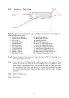
Module Setting: Name the module device and ID that has been connecting the digital input/output device(s) to your system. Device: This column displays the device(s) already installed to the system. ID: Select the number of the I/O port to which you plug the ribbon cable. Input Monitor: The device(s) is turned on if the dot is in red. By triggering the digital input device, the related icon will light up. This is used to check if the device is correctly connected or not. Output Monitor: The device(s) is turned on if the dot is in red. By clicking on the icon, you may trigger the digital device connecting to the system. This can be used to test if the output device is correctly connected. Device Setting Name: Insert the name of the device (input and output). Type: Select the device type from the drop-down menu. N/O: Normal Open. N/C: Normal Close. 6.4 Setting - PTZ Config Basic Setting Advanced Setting Install PTZ cameras following the instruction of the camera manufacturers. A PTZ camera is usually connected to the PC with RS-485/RS-422. Check the box on the camera list to activate the PTZ control function of a PTZ camera. Basic Setting: Select the camera model, com port, baud rate, and address 41
-
 1
1 -
2
-
3
-
4
-
5
-
6
-
7
-
8
-
9
-
10
-
11
-
12
-
13
-
14
-
15
-
16
-
17
-
18
-
19
-
20
-
21
-
22
-
23
-
24
-
25
-
26
-
27
-
28
-
29
-
30
-
31
-
32
-
33
-
34
-
35
-
36
-
37
-
38
-
39
-
 40
40 -
 41
41 -
 42
42 -
 43
43 -
 44
44 -
 45
45 -
 46
46 -
 47
47 -
 48
48 -
 49
49 -
 50
50 -
51
-
52
-
53
-
54
-
55
-
56
-
57
-
58
-
59
-
60
-
61
-
62
-
63
-
64
 |
 |
