TP-Link TL-SL5428E Quick Installation Guide - Page 6
Product Introduction, 1.1 Product Overview, 1.2 Front Panel - switch
 |
UPC - 845973020873
View all TP-Link TL-SL5428E manuals
Add to My Manuals
Save this manual to your list of manuals |
Page 6 highlights
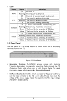
Chapter 1 Product Introduction 1.1 Product Overview TP-LINK L2 Managed Switch provides both Web and Command Line management interface. The Embedded Web Interface supports remote configuration, monitoring and troubleshooting. The EIA-standardized framework together with smart configuration capacity can provide flexible solutions for different scale of networks. The TL-SL5428E provides 24 10/100Mbps auto-negotiation RJ45 ports, 4 10/100/1000Mbps Auto-Negotiation RJ45 ports, 2 SFP (Small Form-Factor Pluggable) module ports and 1 Console port. The SFP1 (SFP2) port and Port 27 (Port 28) are referred to as "combo" ports, which means they cannot be used simultaneously. Port Feature: 10M/100M RJ45 Port Port 1-24 10M/100M/1000M RJ45 Port Port 25-28 Combo Ports RJ45 Port SFP port Port 27 SFP 1 Port 28 SFP 2 1.2 Front Panel Figure 1-1 Front Panel The following parts are located on the front panel of the Switch: ¾ 10/100Mbps Ports: Designed to connect to the device with a bandwidth of 10M or 100M. Each has a corresponding 10/100M LED. ¾ 10/100/1000Mbps Ports: Designed to connect to the device with a bandwidth of 10M, 100M or 1000M. Each has a corresponding 1000M LED. ¾ SFP Ports: Designed to install the SFP module. SFP1 shares the same LED with Port 27 and SFP shares the same LED with Port 28. ¾ Console Port: Designed to connect with the serial port of a computer or terminal for monitoring and configuring the Switch. 1
-
 1
1 -
 2
2 -
 3
3 -
 4
4 -
 5
5 -
 6
6 -
 7
7 -
 8
8 -
 9
9 -
 10
10 -
 11
11 -
 12
12 -
13
-
14
-
15
-
16
-
17
-
18
-
19
-
20
 |
 |
