TRENDnet TV-IP321PI User's Guide - Page 4
Angle Adjustment, Reset Button
 |
View all TRENDnet TV-IP321PI manuals
Add to My Manuals
Save this manual to your list of manuals |
Page 4 highlights
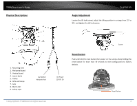
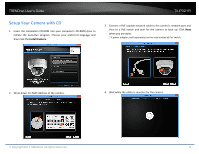
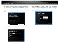
TRENDnet User's Guide Physical Descriptions TV-IP321PI Angle Adjustment Loosen the tilt lock screws, adjust the tilting position in a range from 15 to 90, and tighten the tilt lock screws. 1. Mounting base 2. Horizontal stand 3. Vertical stand 4. Lower dome 5. Cables 6. Infra-red lamps 7. Lens 8. Black Liner 9. Safety rope 10/100 PoE Network Port © Copyright 2014 TRENDnet. All Rights Reserved. Screw Reset Button Push and hold the reset button then power on the camera. Keep holding the reset button for more than 10 seconds to reset configuration to factory default. DC Power 12V DC 1A (Optional) Reset Button 4
-
 1
1 -
 2
2 -
 3
3 -
 4
4 -
 5
5 -
 6
6 -
 7
7 -
 8
8 -
 9
9 -
 10
10 -
11
-
12
-
13
-
14
-
15
-
16
-
17
-
18
-
19
-
20
-
21
-
22
-
23
-
24
-
25
-
26
-
27
-
28
-
29
-
30
-
31
-
32
-
33
-
34
-
35
-
36
-
37
-
38
-
39
-
40
-
41
-
42
-
43
-
44
-
45
-
46
-
47
-
48
-
49
-
50
-
51
-
52
-
53
-
54
-
55
-
56
-
57
-
58
-
59
-
60
 |
 |

TRENDnet User’s Guide
TV-IP321PI
© Copyright 2014 TRENDnet. All Rights Reserved.
4
1.
Mounting base
2.
Horizontal stand
3.
Vertical stand
4.
Lower dome
5.
Cables
6.
Infra-red lamps
7.
Lens
8.
Black Liner
9.
Safety rope
Physical Descriptions
Angle Adjustment
Loosen the tilt lock screws, adjust the tilting position in a range from 15
to
90
, and tighten the tilt lock screws.
Reset Button
Push and hold the reset button then power on the camera. Keep holding the
reset button for more than 10 seconds to reset configuration to factory
default.
Screw
Reset Button
10/100 PoE
Network Port
DC Power
12V DC 1A
(Optional)