Thermador PRG366WH Installation Instructions - Page 21
Backguard installation
 |
View all Thermador PRG366WH manuals
Add to My Manuals
Save this manual to your list of manuals |
Page 21 highlights
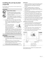
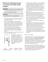
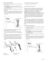
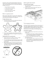
6. Secure the neutral, grounded wire of the supply circuit, to the center stud (silver colored) of the terminal block. 7. Secure the L1 (red) and L2 (black) power leads to the outside corresponding terminal block studs (brass colored). 8. Remove the green ground screw and serrated washer located beneath the terminal block. Screw one end of the included white jumper wire to the chassis beneath the terminal block with the green ground screw. Secure the other end of the wire to the center stud of the terminal block with nut. To install the low backguard 1. Remove the T-20 torx screws in the front face of the included island trim. d c a b 2. Remove the T-20 torx screws securing the trim to the side panels, and the T-20 torx screws securing the piece to the back panel. Lift up to fully remove. a - Red/L1 c - White/neutral b - Ground link wire provided in small bag. d - Black/L2 9. Tighten nuts securely. 10. Reinstall the Terminal Block Cover. Backguard installation 9 WARNING Fingers or hands could get pinched when installing the backguard. Severe injury could result. Use extreme caution and wear thick protective gloves to avoid potential laceration to finger or hand while sliding the backguard down onto the range. 3. Align the back panel of the new accessory with the flanges on the range side panel's right and left rear corners. The backguard is inserted inside the guide channels on the back of the range. 9 WARNING To reduce the risk of fire or injury to persons, check to make sure all packaging has been removed from accessory devices before use. Installation methods will vary upon need. Before you begin read these instructions carefully. Observe all local codes and ordinances. Page. 19
-
 1
1 -
2
-
3
-
4
-
5
-
6
-
7
-
8
-
9
-
10
-
11
-
12
-
13
-
14
-
15
-
 16
16 -
 17
17 -
 18
18 -
 19
19 -
 20
20 -
 21
21 -
 22
22 -
 23
23 -
 24
24 -
 25
25 -
 26
26 -
27
-
28
-
29
-
30
-
31
-
32
-
33
-
34
-
35
-
36
-
37
-
38
-
39
-
40
-
41
-
42
-
43
-
44
-
45
-
46
-
47
-
48
-
49
-
50
-
51
-
52
-
53
-
54
-
55
-
56
-
57
-
58
-
59
-
60
-
61
-
62
-
63
-
64
-
65
-
66
-
67
-
68
-
69
-
70
-
71
-
72
-
73
-
74
-
75
-
76
-
77
-
78
-
79
-
80
 |
 |
