Toshiba Portege R600 PPR65U Maintenance Manual - Page 247
screws, base assembly
 |
View all Toshiba Portege R600 PPR65U manuals
Add to My Manuals
Save this manual to your list of manuals |
Page 247 highlights
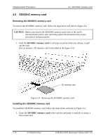
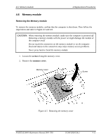
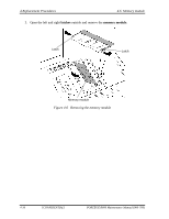
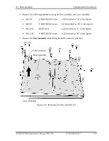
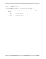
4.7 Base assembly 4 Replacement Procedures 4. Remove the following screws securing the base assembly and cover assembly. • M2×4C S-THIN HEAD screw ×4 (Described as "A" in the figure) • M2×6C S-THIN HEAD screw ×10 (Described as "B" in the figure) • M2.5×6C BIND screw ×2 (Described as "C" in the figure) • M2×2.4C S-THIN HEAD screw ×1 (Described as "D" in the figure) 5. Remove the base assembly while lifting the RJ45 connector side first. (B) (C) (B) (B) (B) (B) RJ45 connector (B) Base assembly (C) (B) (B) (B) (A) (A) (A) (B) (D) (A) Cover assembly Figure 4-8 Removing the base assembly (2) PORTÉGÉ R600 Maintenance Manual (960-709) [CONFIDENTIAL] 4-19
-
 1
1 -
2
-
3
-
4
-
5
-
6
-
7
-
8
-
9
-
10
-
11
-
12
-
13
-
14
-
15
-
16
-
17
-
18
-
19
-
20
-
21
-
22
-
23
-
24
-
25
-
26
-
27
-
28
-
29
-
30
-
31
-
32
-
33
-
34
-
35
-
36
-
37
-
38
-
39
-
40
-
41
-
42
-
43
-
44
-
45
-
46
-
47
-
48
-
49
-
50
-
51
-
52
-
53
-
54
-
55
-
56
-
57
-
58
-
59
-
60
-
61
-
62
-
63
-
64
-
65
-
66
-
67
-
68
-
69
-
70
-
71
-
72
-
73
-
74
-
75
-
76
-
77
-
78
-
79
-
80
-
81
-
82
-
83
-
84
-
85
-
86
-
87
-
88
-
89
-
90
-
91
-
92
-
93
-
94
-
95
-
96
-
97
-
98
-
99
-
100
-
101
-
102
-
103
-
104
-
105
-
106
-
107
-
108
-
109
-
110
-
111
-
112
-
113
-
114
-
115
-
116
-
117
-
118
-
119
-
120
-
121
-
122
-
123
-
124
-
125
-
126
-
127
-
128
-
129
-
130
-
131
-
132
-
133
-
134
-
135
-
136
-
137
-
138
-
139
-
140
-
141
-
142
-
143
-
144
-
145
-
146
-
147
-
148
-
149
-
150
-
151
-
152
-
153
-
154
-
155
-
156
-
157
-
158
-
159
-
160
-
161
-
162
-
163
-
164
-
165
-
166
-
167
-
168
-
169
-
170
-
171
-
172
-
173
-
174
-
175
-
176
-
177
-
178
-
179
-
180
-
181
-
182
-
183
-
184
-
185
-
186
-
187
-
188
-
189
-
190
-
191
-
192
-
193
-
194
-
195
-
196
-
197
-
198
-
199
-
200
-
201
-
202
-
203
-
204
-
205
-
206
-
207
-
208
-
209
-
210
-
211
-
212
-
213
-
214
-
215
-
216
-
217
-
218
-
219
-
220
-
221
-
222
-
223
-
224
-
225
-
226
-
227
-
228
-
229
-
230
-
231
-
232
-
233
-
234
-
235
-
236
-
237
-
238
-
239
-
240
-
241
-
 242
242 -
 243
243 -
 244
244 -
 245
245 -
 246
246 -
 247
247 -
 248
248 -
 249
249 -
 250
250 -
 251
251 -
 252
252 -
253
-
254
-
255
-
256
-
257
-
258
-
259
-
260
-
261
-
262
-
263
-
264
-
265
-
266
-
267
-
268
-
269
-
270
-
271
-
272
-
273
-
274
-
275
-
276
-
277
-
278
-
279
-
280
-
281
-
282
-
283
-
284
-
285
-
286
-
287
-
288
-
289
-
290
-
291
-
292
-
293
-
294
-
295
-
296
-
297
-
298
-
299
-
300
-
301
-
302
-
303
-
304
-
305
-
306
-
307
-
308
-
309
-
310
-
311
-
312
-
313
-
314
-
315
-
316
-
317
-
318
-
319
-
320
-
321
-
322
-
323
-
324
-
325
-
326
-
327
-
328
-
329
-
330
-
331
-
332
-
333
-
334
-
335
-
336
-
337
-
338
-
339
-
340
-
341
-
342
-
343
-
344
-
345
-
346
-
347
-
348
-
349
-
350
-
351
-
352
-
353
-
354
-
355
-
356
-
357
-
358
-
359
-
360
-
361
-
362
-
363
-
364
-
365
-
366
-
367
-
368
-
369
-
370
-
371
-
372
-
373
-
374
-
375
-
376
-
377
-
378
-
379
-
380
-
381
-
382
-
383
-
384
-
385
-
386
-
387
-
388
-
389
-
390
-
391
-
392
-
393
-
394
-
395
-
396
-
397
-
398
-
399
-
400
-
401
-
402
-
403
-
404
-
405
-
406
-
407
-
408
-
409
-
410
 |
 |
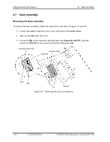
4.7
Base assembly
4 Replacement Procedures
4.
Remove the following
screws
securing the base assembly and cover assembly.
•
M2
×
4C
S-THIN HEAD screw
×
4 (Described as “A” in the figure)
•
M2
×
6C
S-THIN HEAD screw
×
10 (Described as “B” in the figure)
•
M2.5
×
6C
BIND screw
×
2 (Described as “C” in the figure)
•
M2
×
2.4C
S-THIN HEAD screw
×
1 (Described as “D” in the figure)
5.
Remove the
base assembly
while
lifting the RJ45 connector side first.
(B)
(B)
(B)
(B)
(B)
(B)
(B)
(C)
(C)
(A)
(A)
(A)
(A)
Cover assembly
(D)
(B)
(B)
(B)
RJ45 connector
Base assembly
Figure 4-8
Removing the base assembly (2)
PORTÉGÉ R600 Maintenance Manual (960-709)
[CONFIDENTIAL]
4-19