Toshiba R600-SP2801C Maintenance Manual - Page 285
Installing the Cover assembly/LCD assembly
 |
View all Toshiba R600-SP2801C manuals
Add to My Manuals
Save this manual to your list of manuals |
Page 285 highlights
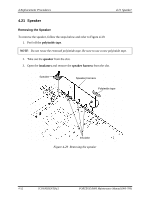
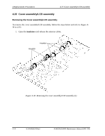
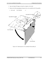
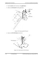
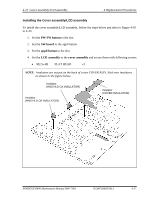
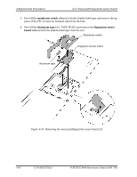
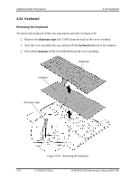
4.22 Cover assembly/LCD assembly 4 Replacement Procedures Installing the Cover assembly/LCD assembly To install the cover assembly/LCD assembly, follow the steps below and refer to Figure 4-30 to 4-33. 1. Set the PW SW button to the slot. 2. Set the SW board to the appli button. 3. Set the appli button to the slot. 4. Set the LCD assembly to the cover assembly and secure them with following screws. • M2.5×4B FLAT HEAD ×2 NOTE: Insulators are not put on the back of a new COVER ASSY. Stick new insulators as shown in the figure below. Insulator (HNS HLD CA INSULATOR) Insulator (HNS HLD CB INSULATOR) Insulator (COVER INSULATOR) PORTÉGÉ R600 Maintenance Manual (960-709) [CONFIDENTIAL] 4-57
-
 1
1 -
2
-
3
-
4
-
5
-
6
-
7
-
8
-
9
-
10
-
11
-
12
-
13
-
14
-
15
-
16
-
17
-
18
-
19
-
20
-
21
-
22
-
23
-
24
-
25
-
26
-
27
-
28
-
29
-
30
-
31
-
32
-
33
-
34
-
35
-
36
-
37
-
38
-
39
-
40
-
41
-
42
-
43
-
44
-
45
-
46
-
47
-
48
-
49
-
50
-
51
-
52
-
53
-
54
-
55
-
56
-
57
-
58
-
59
-
60
-
61
-
62
-
63
-
64
-
65
-
66
-
67
-
68
-
69
-
70
-
71
-
72
-
73
-
74
-
75
-
76
-
77
-
78
-
79
-
80
-
81
-
82
-
83
-
84
-
85
-
86
-
87
-
88
-
89
-
90
-
91
-
92
-
93
-
94
-
95
-
96
-
97
-
98
-
99
-
100
-
101
-
102
-
103
-
104
-
105
-
106
-
107
-
108
-
109
-
110
-
111
-
112
-
113
-
114
-
115
-
116
-
117
-
118
-
119
-
120
-
121
-
122
-
123
-
124
-
125
-
126
-
127
-
128
-
129
-
130
-
131
-
132
-
133
-
134
-
135
-
136
-
137
-
138
-
139
-
140
-
141
-
142
-
143
-
144
-
145
-
146
-
147
-
148
-
149
-
150
-
151
-
152
-
153
-
154
-
155
-
156
-
157
-
158
-
159
-
160
-
161
-
162
-
163
-
164
-
165
-
166
-
167
-
168
-
169
-
170
-
171
-
172
-
173
-
174
-
175
-
176
-
177
-
178
-
179
-
180
-
181
-
182
-
183
-
184
-
185
-
186
-
187
-
188
-
189
-
190
-
191
-
192
-
193
-
194
-
195
-
196
-
197
-
198
-
199
-
200
-
201
-
202
-
203
-
204
-
205
-
206
-
207
-
208
-
209
-
210
-
211
-
212
-
213
-
214
-
215
-
216
-
217
-
218
-
219
-
220
-
221
-
222
-
223
-
224
-
225
-
226
-
227
-
228
-
229
-
230
-
231
-
232
-
233
-
234
-
235
-
236
-
237
-
238
-
239
-
240
-
241
-
242
-
243
-
244
-
245
-
246
-
247
-
248
-
249
-
250
-
251
-
252
-
253
-
254
-
255
-
256
-
257
-
258
-
259
-
260
-
261
-
262
-
263
-
264
-
265
-
266
-
267
-
268
-
269
-
270
-
271
-
272
-
273
-
274
-
275
-
276
-
277
-
278
-
279
-
 280
280 -
 281
281 -
 282
282 -
 283
283 -
 284
284 -
 285
285 -
 286
286 -
 287
287 -
 288
288 -
 289
289 -
 290
290 -
291
-
292
-
293
-
294
-
295
-
296
-
297
-
298
-
299
-
300
-
301
-
302
-
303
-
304
-
305
-
306
-
307
-
308
-
309
-
310
-
311
-
312
-
313
-
314
-
315
-
316
-
317
-
318
-
319
-
320
-
321
-
322
-
323
-
324
-
325
-
326
-
327
-
328
-
329
-
330
-
331
-
332
-
333
-
334
-
335
-
336
-
337
-
338
-
339
-
340
-
341
-
342
-
343
-
344
-
345
-
346
-
347
-
348
-
349
-
350
-
351
-
352
-
353
-
354
-
355
-
356
-
357
-
358
-
359
-
360
-
361
-
362
-
363
-
364
-
365
-
366
-
367
-
368
-
369
-
370
-
371
-
372
-
373
-
374
-
375
-
376
-
377
-
378
-
379
-
380
-
381
-
382
-
383
-
384
-
385
-
386
-
387
-
388
-
389
-
390
-
391
-
392
-
393
-
394
-
395
-
396
-
397
-
398
-
399
-
400
-
401
-
402
-
403
-
404
-
405
-
406
-
407
-
408
-
409
-
410
 |
 |

4.22
Cover assembly/LCD assembly
4 Replacement Procedures
Installing the Cover assembly/LCD assembly
To install the cover assembly/LCD assembly, follow the steps below and refer to Figure 4-30
to 4-33.
1.
Set the
PW SW button
to the slot.
2.
Set the
SW board
to the appli button.
3.
Set the
appli button
to the slot.
4.
Set the
LCD assembly
to the
cover assembly
and secure them with following screws.
•
M2.5
×
4B
FLAT HEAD
×
2
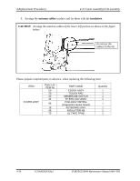
NOTE
:
Insulators are not put on the back of a new COVER ASSY. Stick new insulators
as shown in the figure below.
Insulator
(HNS HLD CB INSULATOR)
Insulator
(COVER INSULATOR)
Insulator
(HNS HLD CA INSULATOR)
PORTÉGÉ R600 Maintenance Manual (960-709)
[CONFIDENTIAL]
4-57