Toshiba RD-XS34SU Owners Manual - Page 14
Rear panel
 |
View all Toshiba RD-XS34SU manuals
Add to My Manuals
Save this manual to your list of manuals |
Page 14 highlights
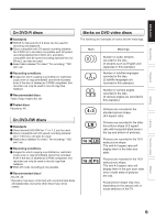
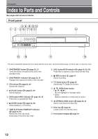
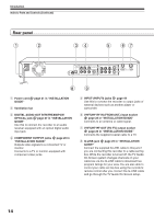
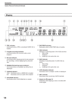
Introduction Index to Parts and Controls (Continued) Rear panel 1 2 34 5 67 8 1 Power cord GUIDE" page 21 in "INSTALLATION 2 Ventilation fan 3 DIGITAL AUDIO OUT BITSTREAM/PCM OPTICAL jack page 27 in "INSTALLATION GUIDE" Use this to connect the recorder to an audio receiver equipped with an optical digital audio input jack. 4 COMPONENT OUTPUT jacks page 26 in "INSTALLATION GUIDE" Outputs video signals to a connected TV or monitor. Connects to a TV or monitor equipped with component video jacks. 9 5 INPUT1/INPUT3 jacks page 44 Use this to connect the recorder to output jacks of external devices such as another player or camcorder. 6 VHF/UHF RF IN (FROM ANT.) input socket page 20 in "INSTALLATION GUIDE" Connects to an antenna or cable signal. 7 VHF/UHF RF OUT (TO TV) output socket page 20 in "INSTALLATION GUIDE" Connects the supplied coaxial cable to a TV. 8 G-LINK jack page 25 in "INSTALLATION GUIDE" Connect the supplied G-LINK cable to this jack if you are connecting this recorder to a cable set top box. While the recorder is turned off, the TV Guide On Screen system changes channels on your cable box via the G-LINK cable to download free program listings for your area. You are also able to control your cable set top box using the recorder's remote control after you connect the G-LINK cable and go through the TV Guide On Screen setup. 14
-
 1
1 -
2
-
3
-
4
-
5
-
6
-
7
-
8
-
 9
9 -
 10
10 -
 11
11 -
 12
12 -
 13
13 -
 14
14 -
 15
15 -
 16
16 -
 17
17 -
 18
18 -
 19
19 -
20
-
21
-
22
-
23
-
24
-
25
-
26
-
27
-
28
-
29
-
30
-
31
-
32
-
33
-
34
-
35
-
36
-
37
-
38
-
39
-
40
-
41
-
42
-
43
-
44
-
45
-
46
-
47
-
48
-
49
-
50
-
51
-
52
-
53
-
54
-
55
-
56
-
57
-
58
-
59
-
60
-
61
-
62
-
63
-
64
-
65
-
66
-
67
-
68
-
69
-
70
-
71
-
72
-
73
-
74
-
75
-
76
-
77
-
78
-
79
-
80
-
81
-
82
-
83
-
84
-
85
-
86
-
87
-
88
-
89
-
90
-
91
-
92
-
93
-
94
-
95
-
96
-
97
-
98
-
99
-
100
-
101
-
102
-
103
-
104
-
105
-
106
-
107
-
108
-
109
-
110
-
111
-
112
-
113
-
114
-
115
-
116
-
117
-
118
-
119
-
120
-
121
-
122
-
123
-
124
-
125
-
126
-
127
-
128
-
129
-
130
-
131
-
132
-
133
-
134
-
135
-
136
-
137
-
138
-
139
-
140
-
141
-
142
-
143
-
144
-
145
-
146
-
147
-
148
-
149
-
150
-
151
-
152
-
153
-
154
-
155
-
156
-
157
-
158
-
159
-
160
-
161
-
162
-
163
-
164
-
165
-
166
-
167
-
168
-
169
-
170
-
171
-
172
-
173
-
174
-
175
-
176
-
177
-
178
-
179
 |
 |
