Toshiba Satellite A350 Maintenance Manual - Page 156
Removing the LCD Hinge Assembly, Removing the Hinge Saddle
 |
View all Toshiba Satellite A350 manuals
Add to My Manuals
Save this manual to your list of manuals |
Page 156 highlights
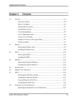
4 Replacement Procedures Figure 4.31 Figure 4.32 Figure 4.33 Figure 4.34 Figure 4.35 Figure 4.36 Figure 4.37 Figure 4.38 Figure 4.39 Figure 4.40 Figure 4.41 Figure 4.42 Figure 4.43 Figure 4.44 Figure 4.45 Figure 4.46 Figure 4.47 Removing the Thermal Module spring screws 4-44 Removing the CPU 4-45 Reapply the Shinetsu 7726 grease on the thermal module and remove the release papers ...4-46 Removing the screws from the rear of the laptop 4-48 Removing the display assembly 4-49 Removing the LCD Bezel Assembly 4-50 Removing the Inverter Board 4-51 Removing the LCD Module from the LCD cover assembly 4-52 Removing the LCD Hinge Assembly 4-53 Removing the LCD module 4-54 Removing the CMOS board and MIC 4-56 Removing the Hinge Saddle 4-57 Removing CRT Board from the logic lower assembly 4-58 Removing the CRT bracket from the CRT board 4-58 Removing the USB Board 4-60 Removing the FM Jack 4-61 Removing the Bluetooth card 4-62 Satellite A350 Maintenance Manual 4-vi
-
 1
1 -
2
-
3
-
4
-
5
-
6
-
7
-
8
-
9
-
10
-
11
-
12
-
13
-
14
-
15
-
16
-
17
-
18
-
19
-
20
-
21
-
22
-
23
-
24
-
25
-
26
-
27
-
28
-
29
-
30
-
31
-
32
-
33
-
34
-
35
-
36
-
37
-
38
-
39
-
40
-
41
-
42
-
43
-
44
-
45
-
46
-
47
-
48
-
49
-
50
-
51
-
52
-
53
-
54
-
55
-
56
-
57
-
58
-
59
-
60
-
61
-
62
-
63
-
64
-
65
-
66
-
67
-
68
-
69
-
70
-
71
-
72
-
73
-
74
-
75
-
76
-
77
-
78
-
79
-
80
-
81
-
82
-
83
-
84
-
85
-
86
-
87
-
88
-
89
-
90
-
91
-
92
-
93
-
94
-
95
-
96
-
97
-
98
-
99
-
100
-
101
-
102
-
103
-
104
-
105
-
106
-
107
-
108
-
109
-
110
-
111
-
112
-
113
-
114
-
115
-
116
-
117
-
118
-
119
-
120
-
121
-
122
-
123
-
124
-
125
-
126
-
127
-
128
-
129
-
130
-
131
-
132
-
133
-
134
-
135
-
136
-
137
-
138
-
139
-
140
-
141
-
142
-
143
-
144
-
145
-
146
-
147
-
148
-
149
-
150
-
 151
151 -
 152
152 -
 153
153 -
 154
154 -
 155
155 -
 156
156 -
 157
157 -
 158
158 -
 159
159 -
 160
160 -
 161
161 -
162
-
163
-
164
-
165
-
166
-
167
-
168
-
169
-
170
-
171
-
172
-
173
-
174
-
175
-
176
-
177
-
178
-
179
-
180
-
181
-
182
-
183
-
184
-
185
-
186
-
187
-
188
-
189
-
190
-
191
-
192
-
193
-
194
-
195
-
196
-
197
-
198
-
199
-
200
-
201
-
202
-
203
-
204
-
205
-
206
-
207
-
208
-
209
-
210
-
211
-
212
-
213
-
214
-
215
-
216
-
217
-
218
-
219
-
220
-
221
-
222
-
223
-
224
-
225
-
226
-
227
-
228
-
229
-
230
-
231
-
232
-
233
-
234
-
235
-
236
-
237
-
238
-
239
-
240
-
241
-
242
-
243
-
244
-
245
-
246
-
247
-
248
-
249
-
250
-
251
-
252
-
253
-
254
-
255
-
256
-
257
-
258
-
259
-
260
-
261
-
262
-
263
-
264
-
265
-
266
-
267
-
268
-
269
-
270
-
271
-
272
-
273
-
274
-
275
-
276
-
277
-
278
 |
 |
