Toshiba Satellite M30X-S171ST Maintenance Manual - Page 137
Top Cover, Removing the Cover
 |
View all Toshiba Satellite M30X-S171ST manuals
Add to My Manuals
Save this manual to your list of manuals |
Page 137 highlights
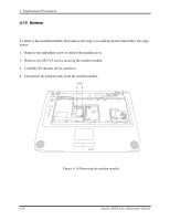
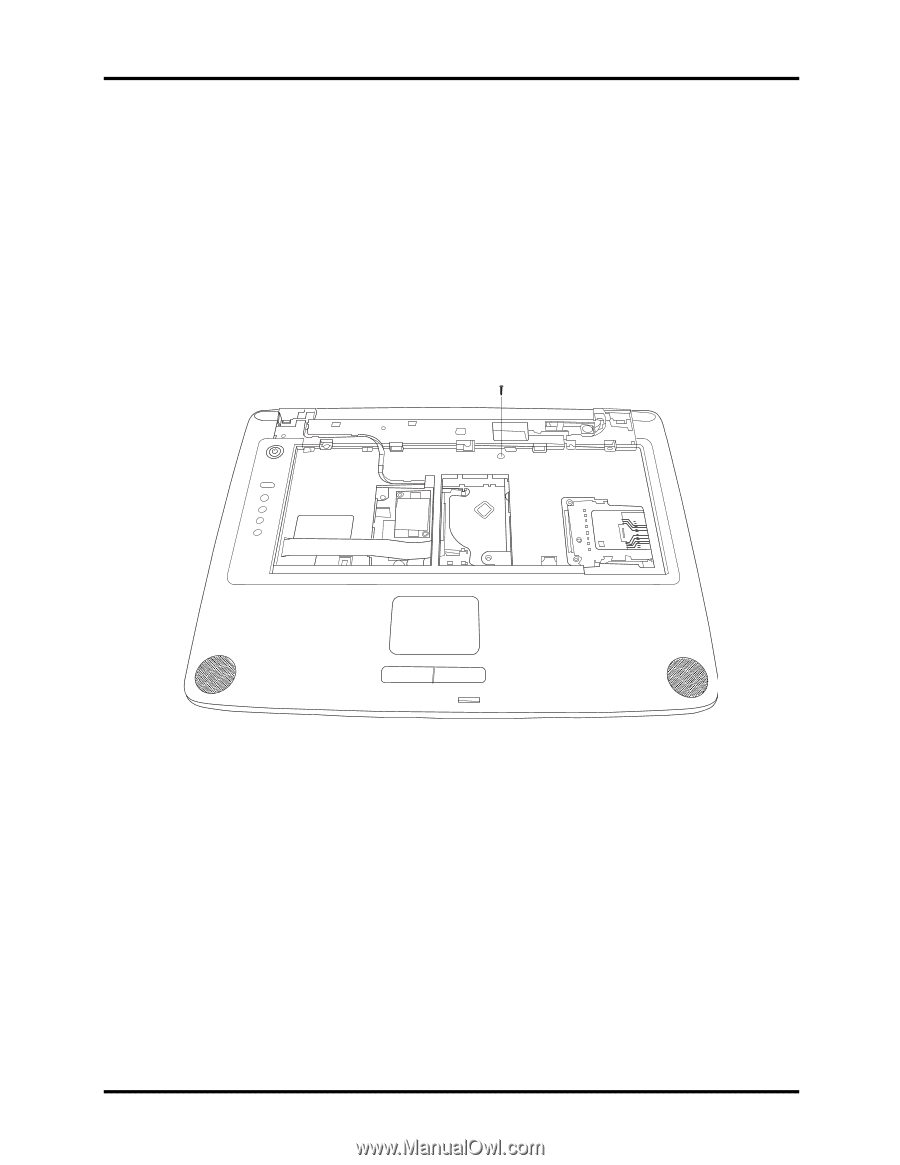
4 Replacement Procedures 4.12 Top Cover Removing the Cover To remove the top cover, first remove the battery pack, display assembly, optical drive module, HDD, and memory module and wireless LAN as described in the preceding sections, then follow the steps below: 1. Remove modem and wireless LAN covers. 2. Remove a M2.5x10 screw securing top cover. M2.5X10 Figure 4-20 Removing the top cover-1 3. Detach the upper FFC cable and touch pad FPC cable on the top chassis. 4. Turn the computer upside down and remove the following twenty one screws. (M2.5X5fifteen screws, M2.5X10-four screws, and M2.5x3-two screws) Satellite M30X Series Maintenance Manual 4-31
-
 1
1 -
2
-
3
-
4
-
5
-
6
-
7
-
8
-
9
-
10
-
11
-
12
-
13
-
14
-
15
-
16
-
17
-
18
-
19
-
20
-
21
-
22
-
23
-
24
-
25
-
26
-
27
-
28
-
29
-
30
-
31
-
32
-
33
-
34
-
35
-
36
-
37
-
38
-
39
-
40
-
41
-
42
-
43
-
44
-
45
-
46
-
47
-
48
-
49
-
50
-
51
-
52
-
53
-
54
-
55
-
56
-
57
-
58
-
59
-
60
-
61
-
62
-
63
-
64
-
65
-
66
-
67
-
68
-
69
-
70
-
71
-
72
-
73
-
74
-
75
-
76
-
77
-
78
-
79
-
80
-
81
-
82
-
83
-
84
-
85
-
86
-
87
-
88
-
89
-
90
-
91
-
92
-
93
-
94
-
95
-
96
-
97
-
98
-
99
-
100
-
101
-
102
-
103
-
104
-
105
-
106
-
107
-
108
-
109
-
110
-
111
-
112
-
113
-
114
-
115
-
116
-
117
-
118
-
119
-
120
-
121
-
122
-
123
-
124
-
125
-
126
-
127
-
128
-
129
-
130
-
131
-
 132
132 -
 133
133 -
 134
134 -
 135
135 -
 136
136 -
 137
137 -
 138
138 -
 139
139 -
 140
140 -
 141
141 -
 142
142 -
143
-
144
-
145
-
146
-
147
-
148
-
149
-
150
-
151
-
152
-
153
-
154
-
155
-
156
-
157
-
158
-
159
-
160
-
161
-
162
-
163
-
164
-
165
-
166
-
167
-
168
-
169
-
170
-
171
-
172
-
173
-
174
-
175
-
176
-
177
-
178
-
179
-
180
-
181
-
182
-
183
-
184
-
185
-
186
-
187
-
188
-
189
-
190
-
191
-
192
-
193
-
194
-
195
-
196
-
197
-
198
-
199
-
200
-
201
-
202
-
203
-
204
-
205
-
206
-
207
-
208
-
209
-
210
-
211
 |
 |
4
Replacement Procedures
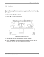
4.12 Top Cover
Removing the Cover
To remove the top cover, first remove the battery pack, display assembly, optical drive module,
HDD, and memory module and wireless LAN as described in the preceding sections, then follow
the steps below:
1.
Remove modem and wireless LAN covers.
2.
Remove a M2.5x10 screw securing top cover.
M2.5X10
Figure 4-20 Removing the top cover-1
3.
Detach the
upper FFC cable and touch pad FPC cable on the top chassis.
4.
Turn the computer upside down and remove the following twenty one screws. (M2.5X5-
fifteen screws, M2.5X10—four screws, and M2.5x3—two screws)
Satellite M30X Series Maintenance Manual
4-31