Toshiba TDP-T250U Owners Manual - Page 10
Parts on the rear panel - video projector
 |
View all Toshiba TDP-T250U manuals
Add to My Manuals
Save this manual to your list of manuals |
Page 10 highlights
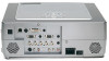
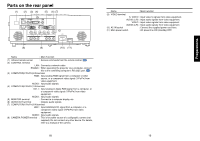
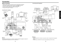
Parts on the rear panel (1) (2) (3) (4) (5) (6) (7) Name : Main Function (9) VIDEO terminal S- VIDEO : Input video S signals from video equipment. AUDIO (L/R) : Input audio signals from video equipment. VIDEO : Input video signals from video equipment. AUDIO (L/R) : Input audio signals from video equipment. (10) AC IN socket : Connect the supplied power cord here. (11) Main power switch : AC power line ON (standby)/OFF. Preparations (8) (9) (10) (11) Name : Main Function (1) Infrared remote sensor : Senses commands from the remote control. p.20 (2) CONTROL terminal LAN : Connects a network cable. RS232C : When operating the projector via a computer, connect this to the controlling computer's RS-232C port. p.56 (3) COMPUTER(Y/PB/PR)2 IN terminal RGB : Input analog RGB signal from a computer or other source, or a component video signal (Y/PB/PR) from video equipment. AUDIO : Input audio signals. (4) COMPUTER(Y/PB/PR)1 IN terminal DVI- I : Input analog or digital RGB signal from a computer, or a component video signal (Y/PB/PR) from video equipment. AUDIO : Input audio signals. (5) MONITOR terminal : Connect to a computer display, etc. (6) AUDIO OUT terminal : Outputs audio signals. (7) COMPUTER(Y/PB/PR)3 IN terminal BNC : Input G/B/R/HD/VD signal from a computer, or a component video signal (Y/PB/PR) from video equipment. AUDIO : Input audio signals. (8) CAMERA POWER terminal : This is for power source of a calligraphic camera (not supplied). Do not connect any other device. For details, refer to a manual of the camera. 18 19
-
 1
1 -
2
-
3
-
4
-
 5
5 -
 6
6 -
 7
7 -
 8
8 -
 9
9 -
 10
10 -
 11
11 -
 12
12 -
 13
13 -
 14
14 -
 15
15 -
16
-
17
-
18
-
19
-
20
-
21
-
22
-
23
-
24
-
25
-
26
-
27
-
28
-
29
-
30
-
31
 |
 |
