Uniden UM385 Owner s Manual - Page 35
Connecting The Radio
 |
View all Uniden UM385 manuals
Add to My Manuals
Save this manual to your list of manuals |
Page 35 highlights
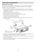
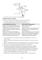
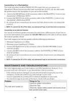
Hex nut Spring washer Washer Mounting surface Mounting bracket Hex bolt 6. Install the radio back into the mounting bracket. CONNECTING THE RADIO To operate correctly, your radio requires two electrical connections: xx providing it with power from the boat's electrical system xx connecting a VHF-FM marine antenna to the antenna connector Power Supply Requirements Nominal 13.8 VDC power supply with a negative ground (10.5 VDC to 16.0 VDC). Power leads should be kept as short as possible. A direct connection to the power supply is ideal. Minimum of #14 AWG copper wire for extensions up to 20 feet, 12 AWG wire for extensions from 20 to 35 feet, or 10 AWG wire for extensions from 35 to 60 feet. VHF Antenna Requirements Male PL-259 connector 50 Ω impedance Minimum 3 foot, 3 dB rated antenna for sailboats or 8 foot, 6 dB rated antenna for powerboats Minimum RG-58 lead-in wire for antenna leads up to 20 feet, RG-8X for antenna leads from 20 to 35 feet, or RG-8U for antenna leads from 35 to 60 feet. 1. Connect the BLACK wire of the power cable to the NEGATIVE (-) side of your power source. 2. Connect the RED wire of the power cable to the POSITIVE (+) side of your power source. ## NOTE: To extend the life of the radio, use waterproof tape to seal electrical connections. 3. Install your antenna according to the manufacturer's instructions. 4. If necessary, consult the FCC guidelines for antenna separation. See Antenna Selection and Installation on page 63 for more details. (In summary, the FCC recommends that antennas up to 3 dB be installed a minimum of 3 feet from any occupied location; antennas over 3 dB should be installed at least 6 feet away.) 5. Connect the PL-259 connector from the antenna lead-in wires to the SO238 connector labeled ANTENNA on the back of your radio. 6. Plug the power cable into the power cable pigtail on the back of your radio. 29
-
 1
1 -
2
-
3
-
4
-
5
-
6
-
7
-
8
-
9
-
10
-
11
-
12
-
13
-
14
-
15
-
16
-
17
-
18
-
19
-
20
-
21
-
22
-
23
-
24
-
25
-
26
-
27
-
28
-
29
-
 30
30 -
 31
31 -
 32
32 -
 33
33 -
 34
34 -
 35
35 -
 36
36 -
 37
37 -
 38
38 -
 39
39 -
 40
40 -
41
-
42
-
43
-
44
-
45
-
46
-
47
-
48
-
49
-
50
-
51
-
52
-
53
-
54
 |
 |
