ViewSonic N4290p N4290P User Guide (English) - Page 19
Rear View of the Product
 |
UPC - 766907300215
View all ViewSonic N4290p manuals
Add to My Manuals
Save this manual to your list of manuals |
Page 19 highlights
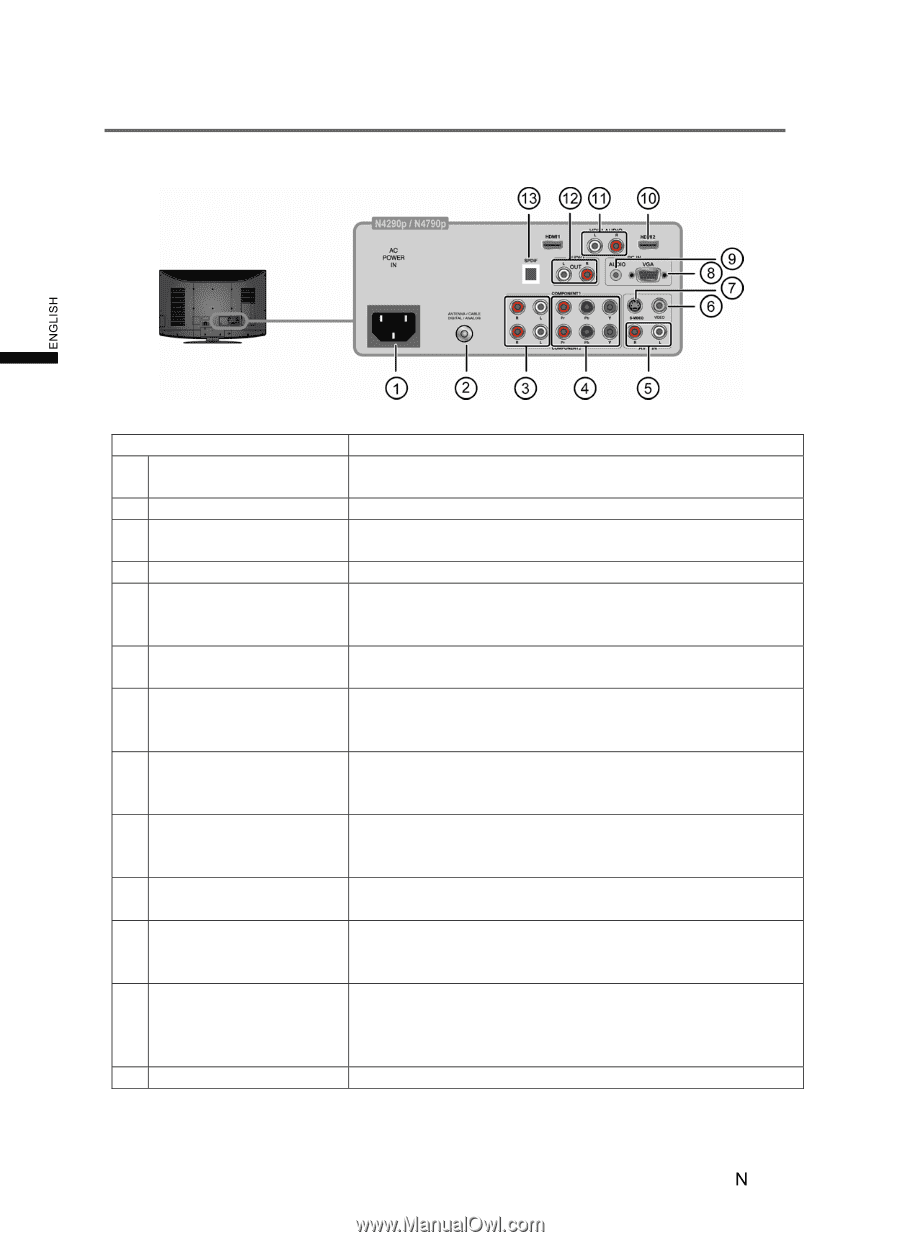
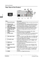
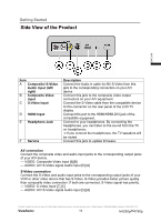
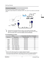
Getting Started Rear View of the Product ENGLISH Item 1 Power (AC input) 2 TV Input Jack 3 YPbPr Audio input (left/ right) 4 YPbPr signal input 5 Composite/ S-Video Audio input (left/ right) 6 Composite Video input 7 S-Video input 8 VGA signal input 9 PC Audio input 10 HDMI Input 11 HDMI Audio (left/ right) 12 Audio Output (left/ right) 13 SPDIF Description Plug-in the supplied AC Power cord and connect to the AC input power source. Connect this jack to your Cable or VHF/UHF antenna Connect the Audio in cable for YPbPr from this jack to the corresponding connectors on your A/V device Connect this jack to the YPbPr output of A/V device. Connect the Audio in cable for AV/ S-Video from this jack to the corresponding connectors on your A/V device Connect this jack to the composite video output connectors on your A/V equipment. Connect the S-Video cable from the compatible device to this connector on the rear panel of the LCD TV display. Connect a 15-pin D-sub RGB cable to the RGB output of your computer and the other end to the RGB input on the rear of the LCD TV display. Connect the RGB Audio Out on your computer to the RGB Audio on the rear of the LCD TV display. This jack is used for PC Audio. Connect this port to the HDMI/HDMI-DVI jack of the compatible equipment. Connect the DVI Audio Out on your computer to the HDMI Audio on the rear of the LCD TV display. This jack is used for DVI Audio. Connect RCA audio cables to "Audio out" on the rear of the LCD TV and the other ends to corresponding audio in connectors on the Amplifier or DVD Home Theater. Connect to a Digital Audio device. Contact ViewSonic service team at: http://www.ViewSonic.com or call our service team: United States 1-800-688-6688, Canada 1-866-463-4775 ViewSonic 12 N4290p/14790p
-
 1
1 -
2
-
3
-
4
-
5
-
6
-
7
-
8
-
9
-
10
-
11
-
12
-
13
-
 14
14 -
 15
15 -
 16
16 -
 17
17 -
 18
18 -
 19
19 -
 20
20 -
 21
21 -
 22
22 -
 23
23 -
 24
24 -
25
-
26
-
27
-
28
-
29
-
30
-
31
-
32
-
33
-
34
-
35
-
36
-
37
-
38
-
39
-
40
-
41
-
42
 |
 |