ViewSonic VG150B Service Manual - Page 17
VG150, April, Version
 |
View all ViewSonic VG150B manuals
Add to My Manuals
Save this manual to your list of manuals |
Page 17 highlights
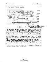
Service Manual VG150 THEORY OF CIRCUIT OPERATION ViewSonic April 1999 - Version 1.0 This product supports timing from VGA to XGA, so the pixel rate is from 25 MHz to 80 MHz. In order to make the phases of sampling clock and video to be closed to each other easily and precisely when user uses the find tune function, the phase delay effect in the high pixel rate is smaller than that in the low pixel rate. The MPU will choose the proper phase adjustment circuit through the pin 4 of IC25, fine tune select. The fine tune control is a PWM signal. When I2C changes the control register the MPU also changes the fine tune control duty cycle. The changed duty cycle will become DC level through R89 and C104. When detecting pixel rate larger than 50 MHz, the MPU will set the fine tune select to high level. If the pixel rate is smaller than 50 MHz, the fine tune select will set to low level. The R52, R59, R80 and C103 are all phase adjustment components. This product supports DDC 1/2B by using 24LC21. The 24LC21 is a 128x 8 bits EEPROM. This chip is designed to use in applications requiring storage and serial transmission of configuration and control information. Two modes of the operation have been implemented, the Transmit Only mode and Bi-Directional mode. Upon power up, this device will be in the Transmit Only mode, sending a serial bit stream of the entire memory array contents, clocked by the VCLK pin. A valid high to low transition on the SCL pin will cause the devise to enter the Bi-Directional mode with byte selectable read/write capability of the memory array. Page 14 raillideifilifTY6Weifrojijoi
-
 1
1 -
2
-
3
-
4
-
5
-
6
-
7
-
8
-
9
-
10
-
11
-
 12
12 -
 13
13 -
 14
14 -
 15
15 -
 16
16 -
 17
17 -
 18
18 -
 19
19 -
 20
20 -
 21
21 -
 22
22 -
23
-
24
-
25
-
26
-
27
-
28
-
29
-
30
-
31
-
32
-
33
-
34
-
35
-
36
-
37
-
38
-
39
-
40
-
41
-
42
-
43
-
44
-
45
-
46
-
47
-
48
-
49
-
50
-
51
-
52
-
53
-
54
-
55
-
56
-
57
-
58
-
59
-
60
-
61
-
62
 |
 |
