ViewSonic VG150B Service Manual - Page 9
Service, Manual, ViewSonic, ASSIGNMENT
 |
View all ViewSonic VG150B manuals
Add to My Manuals
Save this manual to your list of manuals |
Page 9 highlights
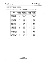
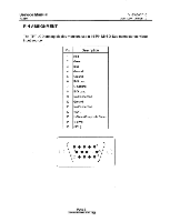
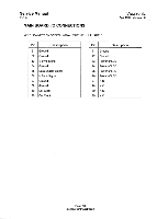
Service Manual VG150 PIN ASSIGNMENT ViewSonic April 1999 - Version 1.0 The TFT LCD analog display monitors use a 15 Pin Mini D-Sub connector as video input source. Pin Description 1 Red 2 Green 3 Blue 4 Ground 5 Ground 6 R-Ground 7 G-Ground 8 B-Ground 9 No Connection 10 Ground 11 No Connection 12 (SDA) 13 H-Sync (Composite Sync) 14 V-Sync 15 (SCL) 1 5 60 • 4110 O 010 1 15 Page 6 raiifilreiiiiirD6Woiropy;
-
 1
1 -
2
-
3
-
 4
4 -
 5
5 -
 6
6 -
 7
7 -
 8
8 -
 9
9 -
 10
10 -
 11
11 -
 12
12 -
 13
13 -
 14
14 -
15
-
16
-
17
-
18
-
19
-
20
-
21
-
22
-
23
-
24
-
25
-
26
-
27
-
28
-
29
-
30
-
31
-
32
-
33
-
34
-
35
-
36
-
37
-
38
-
39
-
40
-
41
-
42
-
43
-
44
-
45
-
46
-
47
-
48
-
49
-
50
-
51
-
52
-
53
-
54
-
55
-
56
-
57
-
58
-
59
-
60
-
61
-
62
 |
 |

Service
Manual
VG150
ViewSonic
April
1999
-
Version
1.0
PIN
ASSIGNMENT
The TFT
LCD
analog
display
monitors
use
a
15
Pin
Mini
D
-Sub
connector
as
video
input
source.
Pin
Description
1
Red
2
Green
3
Blue
4
Ground
5
Ground
6
R
-Ground
7
G
-Ground
8
B
-Ground
9
No
Connection
10
Ground
11
No
Connection
12
(SDA)
13
H
-Sync
(Composite
Sync)
14
V
-Sync
15
(SCL)
1.
.
• •
•5
60
•
4110
O
010
1
)
• • • •
15
Page
6
raiifilreiiiiirD6Woiropy;