ViewSonic VG150B Service Manual - Page 21
OSD_Intensity=0
 |
View all ViewSonic VG150B manuals
Add to My Manuals
Save this manual to your list of manuals |
Page 21 highlights
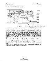
Service Manual VG150 ViewSonic April 1999 - Version 1.0 THEORY OF CIRCUIT OPERATION OSD mixer In the OSD mixer block, the AM100 mixes the normal output RGB signal with the OSD signal. The OSD output data is generated based on the R_OSD G_OSD and B_OSD pins as well as the OSD Intensity data in EEPROM entry. When the EN_OSD is active high, the OSD is active, and the AM100 will send the OSD data to the LCD panel. The OSD has 16 different color schemes based on the combinations of the three OSD color pins and the OSD Intensity data. When R_OSD=1, OSD_Intensity=0, the AM100 will output 128 to the output red channel, R_OUT. When R_OSD=1, and OSD Intensity=1, the AM100 will output 255. The same scheme is used for G-OSD to G-OUT and for B-OSD to BOUT. EEPROM interface As mentioned in previous sections, the external EEPROM stores much crucial information for the AM100 internal operations. The AM100 interfaces with the EEPROM through a 2-wire I2C serial interface. The suggested EEPROM device is an industry standard serial-interface EEPROM (24x08). The I2C interface scheme is briefly described here and detail description can be found in many public literatures. Input Mode Dependent Data Symbol W VPW 11 VBP 11 VBP source 11 Target Skip 11 Pixel VSIZE 11 HPW 11 640 640 720 640 800 1024 Description x x x x x x 350 400 400 480 600 768 OOH 20H 40H 60H 80H A0H LCD VSYNC pules width 01H 21H 41H 61H 81H A1H 02H 22H 42H 62H 82H A2H LCD VSYNC back porch 03H 23H 43H 63H 83H A3H (including VPW) 04H 24H 44H 64H 84H A4H LCD VSYNC back porch 05H 25H 45H 64H 85H A5H (source equivalent) =VBP * Line Expansion and round up 06H 26H 46H 66H 86H A6H If VBP can not be converted 07H 27H 47H 66H 87H A7H into source evenly, the leftover is converted into number Of pixels 08H 28H 48H 68H 88H A8H LCD number of line 09H 29H 49H 69H 89H A9H 0AH 2AH 4AH 6AH 8AH AAH LCD HSYNC pules width OBH 2BH 4BH 6BH 8BH ABH Page 18 UdiffidiiitarDoWorCiiiiP
-
 1
1 -
2
-
3
-
4
-
5
-
6
-
7
-
8
-
9
-
10
-
11
-
12
-
13
-
14
-
15
-
 16
16 -
 17
17 -
 18
18 -
 19
19 -
 20
20 -
 21
21 -
 22
22 -
 23
23 -
 24
24 -
 25
25 -
 26
26 -
27
-
28
-
29
-
30
-
31
-
32
-
33
-
34
-
35
-
36
-
37
-
38
-
39
-
40
-
41
-
42
-
43
-
44
-
45
-
46
-
47
-
48
-
49
-
50
-
51
-
52
-
53
-
54
-
55
-
56
-
57
-
58
-
59
-
60
-
61
-
62
 |
 |
