ViewSonic VMP70 VMP70 User Guide (English) - Page 10
Front View - wireless
 |
UPC - 766907419313
View all ViewSonic VMP70 manuals
Add to My Manuals
Save this manual to your list of manuals |
Page 10 highlights
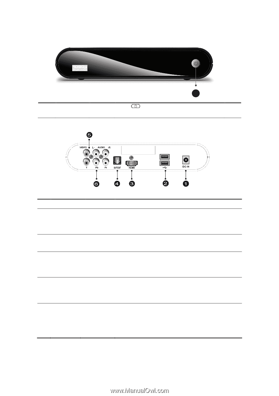
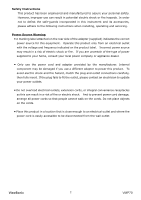
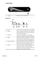
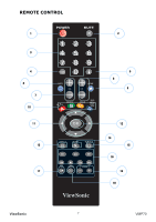
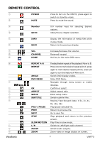
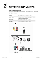
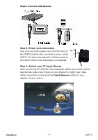
Front View ① Power Back View Press 1 to turn the VMP70 on. ① DC IN ② USB Port ③ HDMI OUT ④ S/PDIF ⑤ AUDIO L/R/ VIDEO ⑥ Y/Pb/Pr Connects to the DC output of the power adapter. Plug the supported USB devices into USB ports, such as USB hard drives, cameras, camcorders and wireless USB dongles. Connects to the HDMI jack on the display; a single cable transmits both audio and video data. Connects the VMP70 to a display or AV receiver that has an optical digital audio port, using an optical digital audio (also called TOSLINK) cable. Connects to the display with the VIDEO IN/ AUDIO L/R IN jacks on the display using VIDEO (Yellow)/ AUDIO L (White)/R (Red) cables. Connect to a Y/Pb/Pr-compatible display using three video (Y/Pb/Pr) and two audio jacks (AUDIO L/R), through a component video cable with green, blue, and red connectors. ViewSonic 6 VMP70
-
 1
1 -
2
-
3
-
4
-
 5
5 -
 6
6 -
 7
7 -
 8
8 -
 9
9 -
 10
10 -
 11
11 -
 12
12 -
 13
13 -
 14
14 -
 15
15 -
16
-
17
-
18
-
19
-
20
-
21
-
22
-
23
-
24
-
25
-
26
-
27
-
28
 |
 |